Firmware
|
Current version |
v1.1.1 |
|
Status |
Completed, ready for production |
|
Supported HW |
EEZ PSU H24005 (Arduino Shield r3B4 or newer) |
|
Simulator |
Windows, Linux, OS X |
|
File repository |
|
|
License |
|
|
Contributions |
The PSU firmware program is an Arduino sketch that must be uploaded to the Arduino board connected to the Arduino shield module. Instructions about firmware downloading, compiling and uploading can be found here.
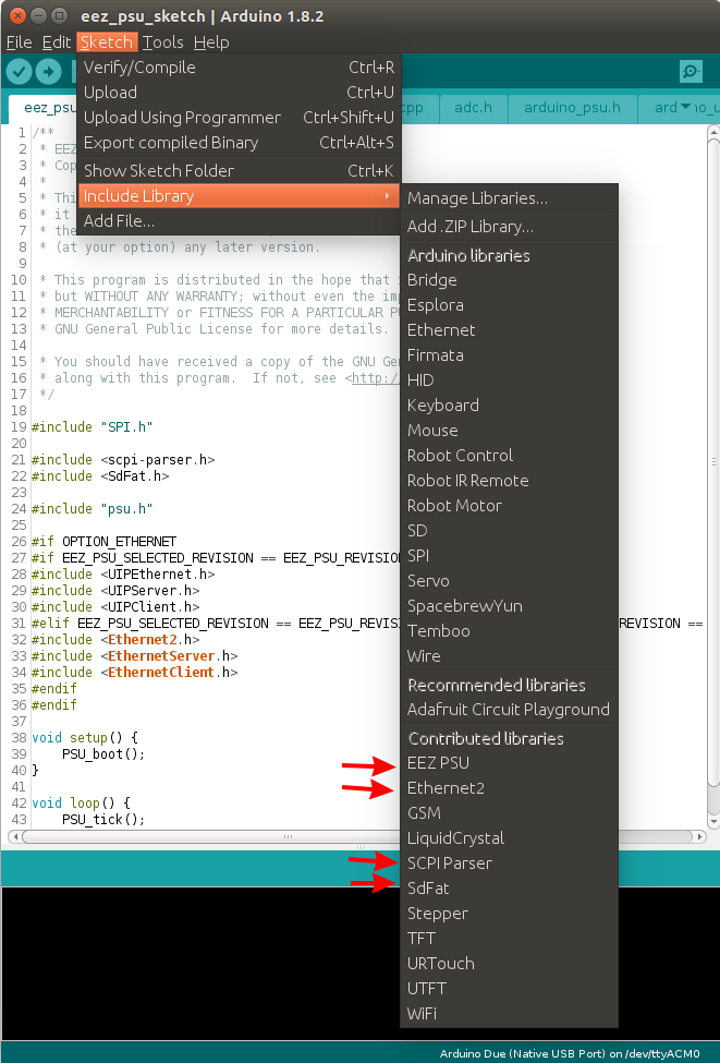
The firmware sketch was tested with the Arduino IDE 1.8.2 and requires four additional libraries that come with the source code distribution. Two of them (i.e. Ethernet2 and SdFat) you have to download and install manually to avoid compilation errors.
When they are all properly installed you should see them in the Arduino IDE as shown on the picture below.
Software simulator
A unique feature of the firmware is the capability of running it without the underlying hardware. There is a software simulator (described in Section 9 of the SCPI reference guide). Another important firmware feature still rare (or almost non-existent) within the DIY/open hardware community is comprehensive support for SCPI. The SCPI represents the core of the firmware; it allows remote control of the bench power supply using various application suites designed for instrument control. For example, one can use the Keysight Command Expert freeware for the bench power supply control and monitoring.
Arduino Due flash memory usage
Sketch uses 433812 bytes (82%) of program storage space. Maximum is 524288 bytes.
|
Item |
Description |
|
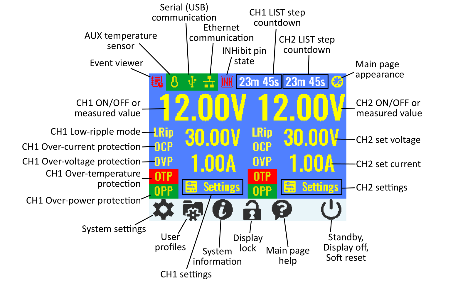
Event viewer |
Event viewer displays list of up to 100 recently recorded events about PSU activity like changing channel’s output states, detected errors, self test errors, entering standby mode, etc. |
|
AUX temperature sensor |
AUX temperature sensor protection settings and state indication (Yellow – not defined/disabled, Green – enabled, Red – tripped). See also SYSTem:TEMPerature:PROTection[:HIGH][:LEVel] |
|
Serial (USB) communication |
Serial communication settings and indicator (Not visible – disabled, Yellow – enabled, Green – communication established). See also SYSTem:COMMunicate:SERial:BAUD |
|
Ethernet communication |
Serial communication settings and indicator (Not visible – disabled, Yellow – enabled, Green – communication established, Red – communication error). See also SYSTem:COMMunicate:ETHernet:ADDRess |
|
INHibit pin state |
Digital input pin INHibit state indicator (Not visible – undefined, White – defined, Red – activated). When PSU is in inhibited state all outputs are disabled and execution of LIST on channels is stopped. See also [SOURce:]DIGital:PIN<n>:FUNCtion |
|
CH1 / CH2 LIST step countdown / DLOG time |
Channel output programming LIST duration (DWELl) time countdown. Visible only for duration of 5 or more seconds formatted as hours/minutes, minutes/seconds or just seconds. See also [SOURce[<n>]]:LIST:DWELl
Note: If internal data logging is running (DLOG), information about its progress is interchanged with LIST duration countdowns. |
|
Main page appearance |
Change main page appearance from numeric (default view, Fig. 2) to bar-graph horizontal, bar-graph vertical or YT-view (Fig. 3). See also DISPlay:VIEW |
|
Channel ON/OFF or measured value |
Use this area to enable (ON) or disable (OFF) channel output. When default appearance is selected measured output voltage is displayed when channel is in constant current (CC) mode or measured output current when channel is in constant voltage (CV) mode. If unregulated (UR) mode is detected, this value will be painted red. See also OUTPut[:STATe] and OUTPut:MODE? |
|
Channel Low-ripple mode |
Low ripple mode settings and indicator (Yellow – not active, Green – active). See also [SOURce[<n>]]:LRIPple |
|
Channel Over-current protection |
Over-current protection (and limit) settings and indicator (Yellow – not defined, Green – enabled, Red – tripped). See also [SOURce[<n>]]:CURRent:PROTection:STATe |
|
Channel Over-voltage protection |
Over-voltage protection (and limit) settings and indicator (Yellow – not defined, Green – enabled, Red – tripped). See also [SOURce[<n>]]:VOLTage:PROTection:STATe |
|
Channel Over-temperature protection |
Over-temperature protection (and limit) settings and indicator (Yellow – not defined, Green – enabled, Red – tripped). See also SYSTem:TEMPerature:PROTection[:HIGH][:LEVel] |
|
Channel Over-power protection |
Over-power protection (and limit) settings and indicator (Yellow – not defined, Green – enabled, Red – tripped). See also [SOURce[<n>]]:POWer:PROTection:STATe |
|
Channel set voltage |
Output voltage settings. See also [SOURce[<n>]]:VOLTage |
|
Channel set current |
Output current settings. See also [SOURce[<n>]]:CURRent |
|
System settings |
System settings provided on two pages: Page (1): AUX temperature sensor, System protection, Trigger, Digital I/O, Date and time, Encoder Page (2): Serial (USB), Ethernet, Channel calibration, Display, Sound, System password |
|
User profiles |
User profile settings. See also *SAV, MEMory:STATe:CATalog |
|
Channel settings |
Channels settings: Protections, Trigger, Advanced, Information. When channels are in tracking mode or coupled in series or parallel, only one Settings option will be available and values for both channels will be presented on Information page. |
|
System information |
System information provided on two pages: Page (1): total on time, last on time, measured temperature on AUX sensor, fan speed, firmware version, serial number Page (2): CPU board (Arduino Shield) revision, Ethernet controller, CH1/CH2 Power boards revisions, SCPI version |
|
Display lock |
Lock/unlock local display. To unlock system password will be required if defined. See also SYSTem:KLOCk and SYSTem:PASSword:NEW |
|
Main page help |
Main page basic help |
|
Standby, Display off, Soft reset |
Shows menu with options for entering Standby mode (SYSTem:POWer), switching TFT local display off (DISPlay[:WINdow][:STATe]) or perform soft reset (*RST). If Standby mode is entered, you have to tap anywhere on the screen and hold it for few seconds for powering the PSU back. |
|
Version |
Description |
Release |
|
M1 |
SCPI compliant firmware for the power supply as an SCPI device class that includes programming of voltage, current, OVP (over-voltage protection), OCP (over-current protection), OPP (over-power protection) and OTP (over-temperature protection), output measurement, ADC/DAC voltage and current calibration, output control, remote sense control, power up control, system date/time (using RTC), diagnostic reporting, beeper, Ethernet and serial (via USB) communication. It also include support for complex SCPI status registers structure. |
12/2015 |
|
Adds support for a local console (within the PSU) based on a color TFT touch screen display as an input device that removes the requirement for many buttons and switches on the front panel. It also enables better user interaction thanks to use of a “pointing device” (i.e. your finger on the touch-screen) that commercial devices in general still do not offer. Both portrait and landscape TFT display orientation will be supported and display pages will be generated using the EEZ Studio visual toolkit. |
10/2016 |
|
|
Channel coupling (parallel, series) with balancing, channel tracking, AUX temperature sensor OTP settings, fan speed control, negative power monitoring (power sink) for down-programmer protection, system lock/password management. |
12/2016 |
|
|
Encoder support, “YT view” for displaying output values, arbitrary waveform generator, triggers, initial SD card support. |
03/2017 |
|
|
Dual channel current range, a first time installation wizard, improved output value precision. |
05/2017 |
|
|
Digital I/O support, Ethernet settings, serial port settings, support for NTP (real-time clock synchronization). |
06/2017 |
|
|
Calibration bug fix for older Power board’s (r5B9). The native USB port is set as default one. A few minor improvements. |
07/2017 |
|
|
Few minor fixes |
10/2017 |
|
|
SD card file management (SCPI only) and Internal Data logging (SCPI only) that can be managed using the EEZ Studio. Various improvements and bug fixes. |
04/2018 |
|
|
See GitHub Milestones section. |
TBA |
Downloads
Software simulator for the bench power supply firmware. Could be used to test all supported functionality without underlying hardware. For other operating systems please visit our Github pages.
MD5: 5C003C3F728FF21302692D2FCC4D949F
SHA1: D01F7D91D4B2B85A09ED5AF9031D048172D728D4
This manual contains reference information for programming open hardware/open source EEZ H24005 bench power supply over the remote interface using the SCPI programming language.


