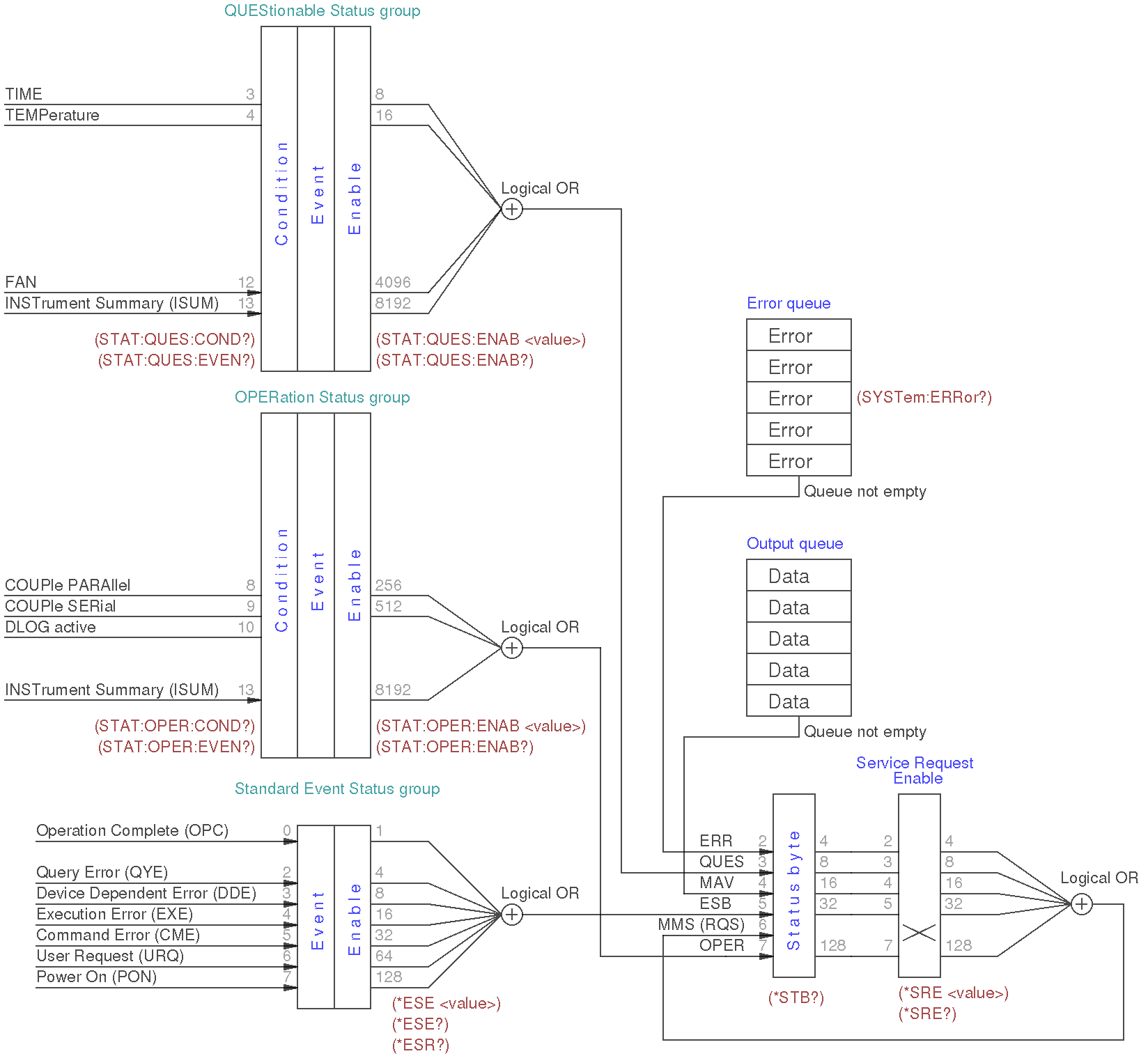
SCPI requires the status mechanism described in Section 11 of IEEE 488.2, including full implementation of the status register structure. Summary of implemented registers structure for the PSU is shown on Fig. 1. (commands used to access registers are written in parentheses).
All SCPI instruments have to implement status registers in the same way. The status system records various instrument conditions in the following register groups:
- the Status Byte register,
- the Standard Event register,
- the QUEStionable Status register group, and
- the OPERation Status register group.
The Status Byte register records high-level summary information reported in the other register groups.
Message interchanging between Controller and Instrument is accomplished by using input buffer and Output queue and Error queue. The length of the Input buffer is 48 characters. Both Output and Error queue can handle up to 20 messages.
3.1. Standard Event Status Register
An status register group is consist of Condition, Event and Enable registers (see Fig. 1):
- The Condition register is a read-only register, which holds the live (unlatched) operational status of the instrument. Reading the Condition register does not clear it.
- The Event register is a read-only that reports defined conditions within the PSU. Bits in an event register are latched. Once an event bit is set, subsequent state changes are ignored. Bits in the Event register are automatically cleared by a query of that register (such as *ESR? or STATus:QUEStionable:EVENt?) or by sending the *CLS (clear status) command. A reset (*RST) or device clear will not clear bits in event registers (See Section 8.2). Querying an event register returns a decimal value which corresponds to the binary-weighted sum of all bits set in the register.
- The ENABle register is used to define which bits of the Event Status register will latch ESB (bit 5) of the Status byte register.
An error status (bit 2, 3, 4 or 5) records one or more errors in the PSU error queue. The SYSTem:ERRor? command can be used to read the error queue.
Implementation of the Standard Event Status register follows IEEE 488.2 Section 11.5.1.1:
|
Bit |
Decimal value |
Description |
|
0 |
1 |
Operation Complete (OPC) – This event bit is generated in response to the *OPC command. It indicates that the PSU has completed all selected pending operations (including *OPC). |
|
1 |
2 |
Not used |
|
2 |
4 |
Query ERROR (QYE) – Query Errors are detected by the Output Queue Control. This event bit indicates that either
Events that generate Query Errors do not generate Execution Errors, Command Errors, or Device-Specific Errors. |
|
3 |
8 |
Device-Specific ERROR (DDE) – This event bit indicates that an error has occurred that is neither a Command Error, a Query Error, nor an Execution Error. A Device-Specific Error is any executed device operation that did not properly complete due to some condition, such as over-range, a self-test or calibration error. Following a Device-Specific Error, the PSU will continue to process the input stream. Events that generate Device-Specific Errors do not generate Command Errors, Query Errors, or Execution Errors. |
|
4 |
16 |
Execution ERROR (ERR) – This event bit indicates that:
Following an Execution Error, the PSU will continue parsing the input stream. Execution Errors will be reported by the PSU after rounding and expression evaluation operations have taken place. Rounding a numeric data element, for example, will not be reported as an Execution Error. Events that generate Execution Errors do not generate Command Errors, Query Errors, or Device-Specific Errors. |
|
5 |
32 |
Command ERROR (CME) – Command Errors are detected by the parser. This event bit indicates that one of the following events has occurred:
When the PSU detects a Command Error, parser synchronization may be lost. When a Command Error is detected, any prior parsable elements of the same <PROGRAM MESSAGE> will be executed. That is also true for all parsable elements that follows after detected Command Error.
The Command Error bit not be set to report any other device-specific condition. Events that are reported as Command Errors cannot be reported as Execution Errors, Query Errors, or Device-Specific Errors. |
|
6 |
64 |
User Request (URQ) – This event bit indicates that the PSU input device (TFT Touch screen) has been for any reason activated. The setting of this event-bit occur regardless of the IEEE 488.1 Remote/Local state of the device (not implemented yet) |
|
7 |
128 |
Power On (PON) – This event bit indicates that an off-to-on transition has occurred in the device’s power supply. See also SYSTem:POWer. |
|
8 – 15 |
– |
Not used, always zero |
The Status Byte summary register reports conditions from the other status registers (see Fig. 1). Query data that is waiting in the PSU’s output buffer is immediately reported through the "Message Available" (MAV) bit (bit 4) of the Status Byte register. Bits in the summary register are NOT latched. Clearing an event register will clear the corresponding bits in the Status Byte summary register. Reading all messages in the output buffer, including any pending queries, will clear the message available bit (MAV).
The Status Byte summary register is cleared when the *CLS (clear status) command has been executed.
The Status Byte enable register (request service) is cleared when the *SRE 0 command has been executed.
Querying the Standard Event register (*ESR? command) will clear only bit 5 (ESR) in the Status Byte summary register. For example, 24 (8 + 16) is returned when you have queried the status of the Status Byte register, QUES and MAV conditions have occurred.
|
Bit |
Decimal value |
Description |
|
0 – 1 |
– |
Not used, always zero |
|
2 |
4 |
ERR – Error queue bit indicates that one or more errors have been stored in the Error queue. |
|
3 |
8 |
QUES – One or more bits are set in the QUEStionable Status register (bits must be enabled in the enable register). |
|
4 |
16 |
MAV – The Message Available bit indicates whether or not the Output Queue is empty. Whenever the device is ready to accept a request by the controller to output data bytes, the MAV is TRUE. The MAV is FALSE when the Output Queue is empty. This bit is used to synchronize information exchange with the controller. The controller can, for example, send a query command to the device and then wait for MAV to become TRUE. |
|
5 |
32 |
ESB – One or more bits are set in the Standard Event register (bits must be enabled in the enable register, see *ESE command). |
|
6 |
64 |
MMS – Master Status summary bit indicates that one or more bits are set in the Status Byte Register (bits must be enabled, see *SRE command). Also used to indicate a request for service (RQS). |
|
7 |
128 |
OPER – One or more bits are set in the OPERation Status register. |
3.3. OPERation Status Register
The OPERation status register contains conditions which are part of the instrument’s normal operation.
Each channel of the PSU is considered as separate "instrument". The two logical outputs (channels) of the PSU include an INSTrument summary status register and an individual instrument ISUMmary register for each logical output.
The bit definition of OPERation Status register shown on Fig.1.:
|
Bit |
Decimal value |
Description |
|
0 – 7 |
– |
Not used, always zero |
|
8 |
256 |
COUPle PARAllel indicate that PSU’s channels are connected in parallel. |
|
9 |
512 |
COUPle SERial indicate that PSU’s channels are connected in serial. |
|
10 |
1024 |
Internal data logging is in progress. |
|
11 – 12 |
– |
Not used, always zero |
|
13 |
8192 |
INSTrument Summary Bit – One of n multiple logical instruments is reporting OPERational status. |
|
14 – 15 |
– |
Not used, always zero |
The Event Status Enable register is cleared when the STAT:EVEN:ENAB 0 command is executed. The *CLS command can be also used to clear the register.
3.3.1. Operation INSTrument Status register
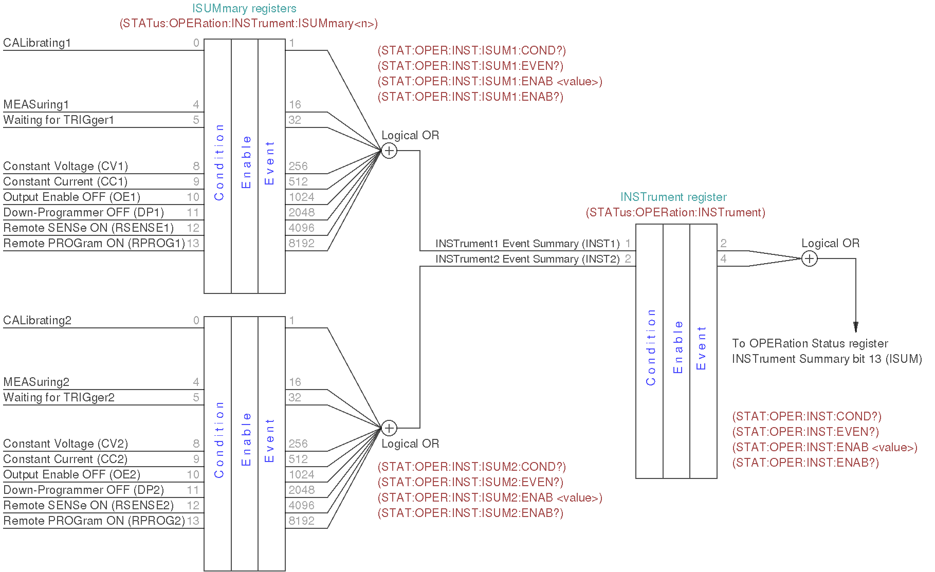
The bit definition of OPERation INSTrument Status register shown on Fig.2.:
|
Bit |
Decimal value |
Description |
|
0 |
– |
Not used, always zero |
|
1 |
2 |
INST1 – Instrument1 summary bit indicate that one or more bits are changed in the Channel 1 OPERation INSTrument Summary register |
|
2 |
4 |
INST2 – Instrument2 summary bit indicate that one or more bits are changed in the Channel 2 OPERation INSTrument Summary register |
|
3 – 15 |
– |
Not used, always zero |
3.3.2. Operation Instrument SUMmary status register
The ISUMmary registers report to the INSTrument register, which in turn reports to bit 13 of the Operation Status register. This is illustrated on Fig. 2. Using such a status register configuration allows a status event to be cross- referenced by output channel and type of event. The INSTrument register indicates which channel(s) have generated an event. The ISUMmary register represent a pseudo-operation Status register for a particular logical output.
The bit definition of OPERation INSTrument ISUMmary Status register shown on Fig.2.:
|
Bit |
Decimal value |
Description |
|
0 |
1 |
CALibrating – Channel is performing calibration |
|
1 – 3 |
– |
Not used, always zero |
|
4 |
16 |
MEASuring – Channel is performing measurement (not implemented yet) |
|
5 |
32 |
Waiting for TRIGger – Channel is waiting for the trigger event |
|
6 – 7 |
– |
Not used, always zero |
|
8 |
256 |
CV – Channel is entered CV operation mode |
|
9 |
512 |
CC – Channel is entered CC operation mode |
|
10 |
1024 |
OE – Output is switched off |
|
11 |
2048 |
DP – Down-programmer is switched off |
|
12 |
4096 |
RSENSE – Remote voltage sense is switched on |
|
13 |
8192 |
RPROG – Remote voltage programming is switched on |
|
14 – 15 |
– |
Not used, always zero |
3.4. QUEStionable Status Register
The Questionable Status register provides information about unexpected operations of the PSU. Each channel of the PSU is considered as separate "instrument". The two logical outputs (channels) of the PSU include an INSTrument summary status register and an individual instrument ISUMmary register for each logical output.
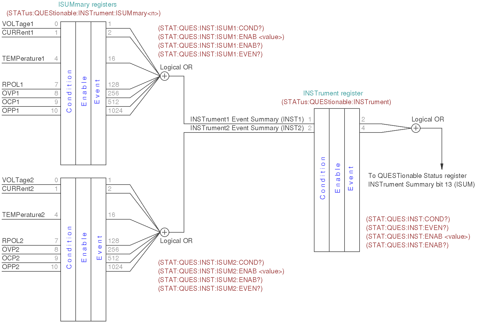
The ISUMmary registers report to the INSTrument register, which in turn reports to bit 13 of the Questionable Status register. This is illustrated on Fig. 3. Using such a status register configuration allows a status event to be cross-referenced by output channel and type of event. The INSTrument register indicates which channel(s) have generated an event. The ISUMmary register represent a pseudo-Questionable Status register for a particular logical output.
For example, if one of the two channels is in constant voltage (CV) mode and due to an overload looses regulation, bit 13 is set (latched). To read the register, the command STATus:QUEStionable? is required. To make use of bit 13 (ISUM), enable register must be correctly set. The command STAT:QUES:INST:ENAB 6 (2 + 4) has to be send to enable the Questionable instrument register, followed by the command STAT:QUES:INST:ISUM<n>:ENAB 19 for each channel to enable the QUEStionable INSTrument SUMmary register, where n is 1 or 2.
Bit definition for QUEStionable Status register shown on Fig.1.:
|
Bit |
Decimal value |
Description |
|
0 – 2 |
– |
Not used, always zero |
|
3 |
8 |
TIME – indicate abnormal time/date situation due to RTC failure or conflict between current and time/date retrieved from the stored configuration. |
|
4 |
16 |
TEMPerature – temperature measurement that use the AUX temperature sensor on the Arduino Shield board require attention (i.e. over-temperature condition is detected, sensor is not functional, etc.). Do not confuse this sensor with that are connected to a PSU channels. |
|
5 – 11 |
– |
Not used, always zero |
|
12 |
4096 |
FAN – cooling fan failure is detected |
|
13 |
8192 |
INSTrument summary, is described later in this chapter in association with multiple logical instruments. |
|
14 – 15 |
– |
Not used, always zero |
The Questionable Status Enable register is cleared when the STAT:QUES:ENAB 0 command is executed. The *CLS command can be also used to clear the register.
3.4.1. Questionable INSTrument Status register
Bit definition for QUEStionable INSTrument register:
|
Bit |
Decimal value |
Description |
|
0 |
– |
Not used, always zero |
|
1 |
2 |
INST1 – Instrument1 summary bit indicate that one or more bits are changed in the Channel 1 OPERation INSTrument Summary register. |
|
2 |
4 |
INST2 – Instrument2 summary bit indicate that one or more bits are changed in the Channel 2 OPERation INSTrument Summary register. |
|
3 – 15 |
– |
Not used, always zero |
3.4.2. Questionable Instrument SUMmary status register
There are two questionable instrument summary registers, one for each PSU output. These registers provide information about voltage and current regulation.
Bit definition for QUEStionable INSTrument SUMmary register:
|
Bit |
Decimal value |
Description |
|
0 |
1 |
VOLTage – This bit is set when the voltage becomes unregulated, therefore a channel enters CC operation mode. If the over-voltage protection (OVP) is activated (see VOLTage:PROTection:STATe) channel output will be switched off. |
|
1 |
2 |
CURRent – This bit is set when the current becomes unregulated, therefore a channel enters CV operation mode. If the over-current protection (OCP) is activated (see CURRent:PROTection:STATe) channel output will be switched off. |
|
2 – 3 |
– |
Not used, always zero |
|
4 |
16 |
TEMPerature – the temperature sensor on the channel power board require attention (i.e. over-temperature condition is detected, sensor is not functional, etc.). Do not confuse this sensor with one that is connected to the Arduino shield board. |
|
5 – 6 |
– |
Not used, always zero |
|
7 |
128 |
RPOL – Remote sense reverse polarity is detected. |
|
8 |
256 |
OVP – Over-voltage protection is activated. The query VOLT:PROT:TRIP? returns value of this bit. See also STAT:QUES. |
|
9 |
512 |
OCP – Over-current protection is activated. The query CURR:PROT:TRIP? returns value of this bit. See also STAT:QUES. |
|
10 |
1024 |
OPP – Over-power protection is activated. The query POW:PROT:TRIP? returns value of this bit. See also STAT:QUES. |
|
11 – 15 |
– |
Not used, always zero |
Please note here that CURRent bit is use for questionable Voltage operating mode and vice versa.
If 0 and 1 bits is true that indicate neither the voltage nor the current is regulated (so-called unregulated or UR mode), and both bits false indicate the PSU channel are off.
To read the register for each PSU channel, the command STAT:QUES:INST:ISUM[<n>]? has to be send, where [<n>] is 1 or 2. If [<n>] is not specified the currently selected channel is used.
Use STAT:QUES:INST:ISUM<n>:COND? to determine operating mode (CV or CC) for the PSU channel (where n is 1 or 2 depending on the output).
The Questionable Status event register is cleared with:
- the *CLS (clear status) command or
- the event register is queried using the STAT:QUES? (status questionable event register) command.
The error queue contains items that include a numerical and textual description of the error or event.
The <Error/event_number> is a unique integer in the range [-32 768, 32 767]. All positive numbers are instrument-dependent. All negative numbers are reserved by the SCPI standard with certain standard error/event codes. The value, zero, is also reserved to indicate that no error or event has occurred.
The second parameter of the full response is a quoted string containing an <Error/event_description>. Each <Error/event_number> has a unique and fixed <Error/event_description> associated with it. An example:
-113,"Undefined header"
The maximum string length of <Error/event_description> plus <Device-dependent_info> is 255 characters. List of all error/event messages can be found in Section 7 of this document.
As errors and events are detected, they are placed in a queue. This queue is first in, first out. If the queue overflows, the last error/event in the queue is replaced with error:
-350,"Queue overflow"
Any time the queue overflows, the least recent errors/events remain in the queue, and the most recent error/event is discarded. Reading an error/event from the head of the queue removes that error/event from the queue, and opens a position at the tail of the queue for a new error/event, if one is subsequently detected.
If the error queue is not empty, bit 2 of the Instrument Summary Status Register is set. A query returns only the oldest error code and associated error description information from the error queue. To return all error codes and associated description information, use repetitive queries until an error value of zero is returned, or until bit 2 of the status register is 0.
The error queue is cleared when any of the following occur (IEEE 488.2, section 11.4.3.4):
- Upon power up
- Upon receipt of a *CLS command
- Upon reading the last error message from the queue


