EEZ DIB AUX Power Supply
|
Current version |
r3B3 |
|
Status |
Completed, ready for production |
|
PCB manufactured |
Yes (r3B3) |
|
PCB assembled |
Yes (r3B3) |
|
BOM |
Yes (TME, Mouser, Digikey, Farnell, RS) |
|
File repository |
https://github.com/eez-open/modular-psu/tree/master/aux-ps |
|
License |
|
|
Contributions |
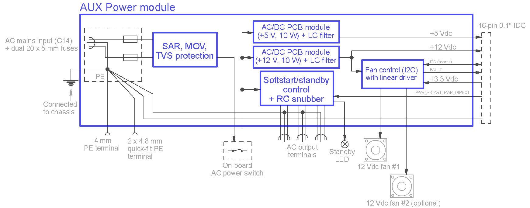
The AUX power supply is used for powering MCU board and peripheral modules inserted into DIB backplane. It consists of the following sections:
- AC IEC C14 inlet with two 20 x 5 mm fuse
- AC power switch
- AC power input protection (TVS, MOV, SAR)
- Standby LED indicator
- In-rush current limitation and standby circuit for AC/DC power modules,
- DC fan controller with I2C interface
- +5 V, +12 V AC/DC modules
- BOOT0 switch
AC input and soft-start/standby
The AUX power module has on-board AC power input, AC switch and AC power distribution to reduce wiring and is the only part that is in direct connection with AC mains voltage.
WARNING: special caution is required when this module is operating.
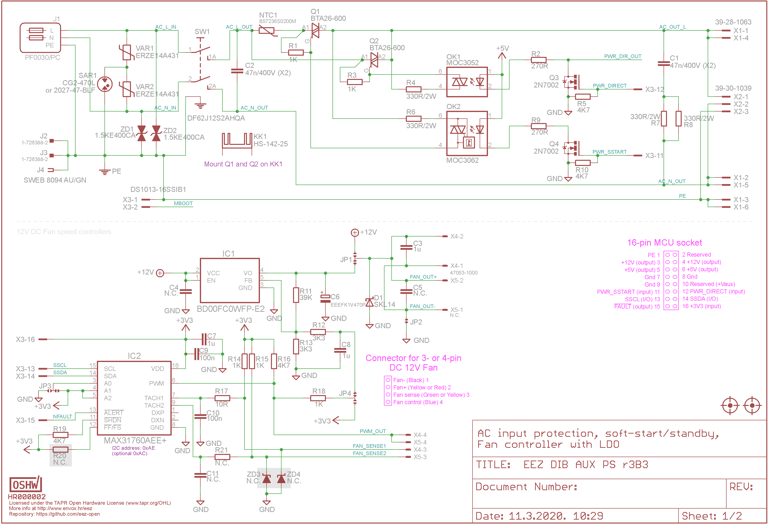
The AC input line protection includes two bidirectional TVSes (ZD1, ZD2), two MOVs (MOV1, MOV2) and a SAR (see Fig. 3). That improves immunity against various spikes and disturbances that can appear on AC mains input. They are specified for 230 VAC and could be modified for better sensitivity if the EEZ BB3 is connected to 115 VAC. The AC IEC inlet contains two replaceable fuses (for both N and L inputs) against overload that could be caused by activation of a line protection item in the first place. Fuse voltage and current ratings have to be selected in accordance with AC mains voltage and number of installed AC/DC power (Mean Well LRS-150F-48) modules for powering peripheral DC power modules (e.g. DCP405, DCM220).
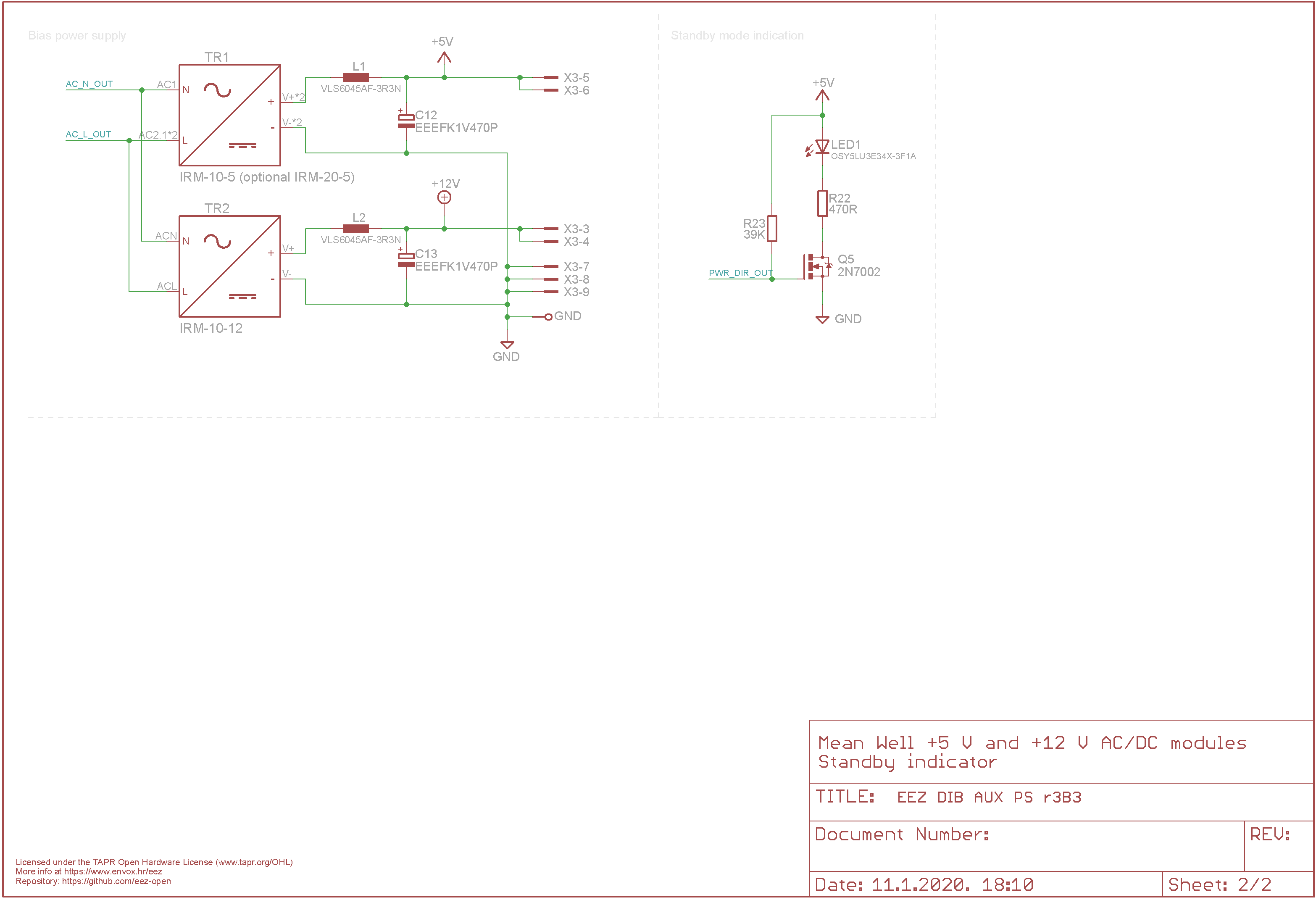
The in-rush current limiter provides soft-start of the AC mains power delivered to up to three AC/DC power modules. It consists of 20 Ω NTC1 that limits in-rush current below 11.5 A for 230 Vac or 5.75 A for 115 Vac when connected in series with load via triac (Q1) controlled from MCU (PWR_SSTART) by opto-triac (OK2). Shortly after the input current settles down, the NTC1 and Q1 are bypassed with another triac (Q2) controlled by PWR_DIRECT signal (via OK1). The load (AC/DC power modules) will stay connected until the EEZ BB3 enters standby mode (initiated by user or fault condition). Therefore, this circuit also provides power-on/standby functionality without need to use the AC mains switch (SW1) on the front panel. The LED1 indicates standby mode.
Note that Q1 and Q2 are controlled with two different type of opto-triac: the OK2 is of a Zero-crossing type and the OK1 is a nonzero-crossing (or random) device. That means that power-up and power-down sequence can only start when the mains voltage is minimal (zero); NTC1 bypassing can happen at any time after the programmed soft-start time passed.
Q1 and Q2 that come in insulated TOP-3 package are mounted on to shared heatsink (KK1) for improved cooling. AC power output has the RC snubber (C1, R7+R8). Connectors X1 (dual) and X2 (single) are used for connecting AC/DC power modules.
DC fan speed control
The DC fan controller (IC2) is used to drive up to two Ø80 mm 12 V DC fans depending of the number of installed power source boards and accompanied AC/DC power modules. Selected MAX31760 is an I2C controller that features precise fan speed control based on the temperature reading as an index to a 48-byte lookup table (LUT) containing user-programmed PWM values. The flexible LUT-based architecture enables the user to program a smooth nonlinear fan speed vs. temperature transfer function to minimize acoustic fan noise. Two tachometer inputs allow measuring the speeds of two fans independently and is used to notify MCU about failure.
The PWM output requires pull-up (R16) and is further filtered (R18, C8) to provide analog signal that define output voltage of the LDO (IC1) that drives the DC fan or two. The voltage difference between input voltage (12 V) and set voltage has to be dissipated on the IC1, but for lower voltage (required for lower fan speed) selected fan draws little current. Therefore it can be efficiently cooled just with the PCB cooper plate as a heatsink.
Information about peripheral modules temperature that will be used to control fans MCU is collecting via I2C from module’s temperature sensors and instruct IC2 about needed fan speed. Since its power consumption is low, it is powered from the MCU board.
AC/DC power modules
Two “off-the-shelf” AC/DC PCB mounted power converters (TR1, TR2) are used to provide +5 V (10 or 20 W) or +12 V (10 W) for powering MCU module, and peripheral modules inserted into DIB backplane. Additional output filtering (L1, C12, and L2, C13) are added to reduce switching noise.
PCB layout
The auxiliary power module is assembled on the 230.5 x 60 mm two-layer PCB. That board dimension is selected intentionally to be in line with EEZ BB3 chassis depth. Therefore, AC inlet can be directly fixed on the chassis rear panel. On the other side, AC switch, standby LED, and PE terminal (J4), can be exposed on the front panel to reduce required wiring.
There are a few places on the PCB that deserve special mention:
- proper spacing between the opto-triac’s low and high-voltage sections,
- adequate (and sufficiently adequate to be safe!) AC power traces width and spacing
- no trace routed on the top side in the KK1 heatsink area.


