EEZ H24005 group buy kit assembly instructions
A work in progress (Draft 0.9) – PDF version for download is available at the page end
Introduction
Instructions presented in this document are related to Complete kit for EEZ H24005 power supply offered through crowdfunding campaign. If you intended to build one from the scratch e.g. having only bare PCBs to start with, please refer to EEZ PSU H24005 building instructions (r5B12).
The EEZ H24005 (PSU) kit is not an end user product. As such it was not put into any conformance testing and it may not comply with some or any technical or legal requirement that are applicable to finished products including, without limitation, directives regarding electromagnetic compatibility, recycling (WEEE), FCC, CE, or UL. Assembling and using the PSU requires an understanding of electronic circuits and basic computer programming skills.
If you need assistance, please contact us using this form or post your problem on the EEVblog forum here. Or, feel free to open a New issue on GitHub here, but please check first to see whether a similar issue already exists).
Only tool required for kit mechanical assembly is medium Phillips head screwdriver. Of course, a multimeter for checking wiring and voltage on few points during the assembly is recommended.
Before you start
We made our best effort to make your EEZ H24005 kit complete and functional. But, please note that due to limited resources kit is not completely and thoroughly tested. Basic testing were performed on the following parts:
- Core modules (i.e. Aux power module, Power boards and Arduino Shield)
- Arduino Due (plugged into Arduino Shield)
- 3.2” TFT touchscreen display (plugged into Arduino Shield)
Core modules are tested on our “testbed” but not with using wire harness and AC/DC modules that comes with your kit. Therefore it’s highly recommended that you check visually, mechanically and with ohmmeter if cables are properly assembled before you proceed with final assembling (consult Wire harness section). Please also check Troubleshooting section at the end of this document.
Basic testing covered communication over Ethernet, fan control, power control, touchscreen functionality, beeper, TFT display and output voltage and current programming in a whole range (i.e. up to 40 V and 5 A with connected load and not calibrated!).
AC/DC modules are capable of working with both 115 and 230 Vac. Few of them are randomly selected and tested on 230 Vac. Therefore it would be a wise step to test them before they’re wired with the rest of the unit.
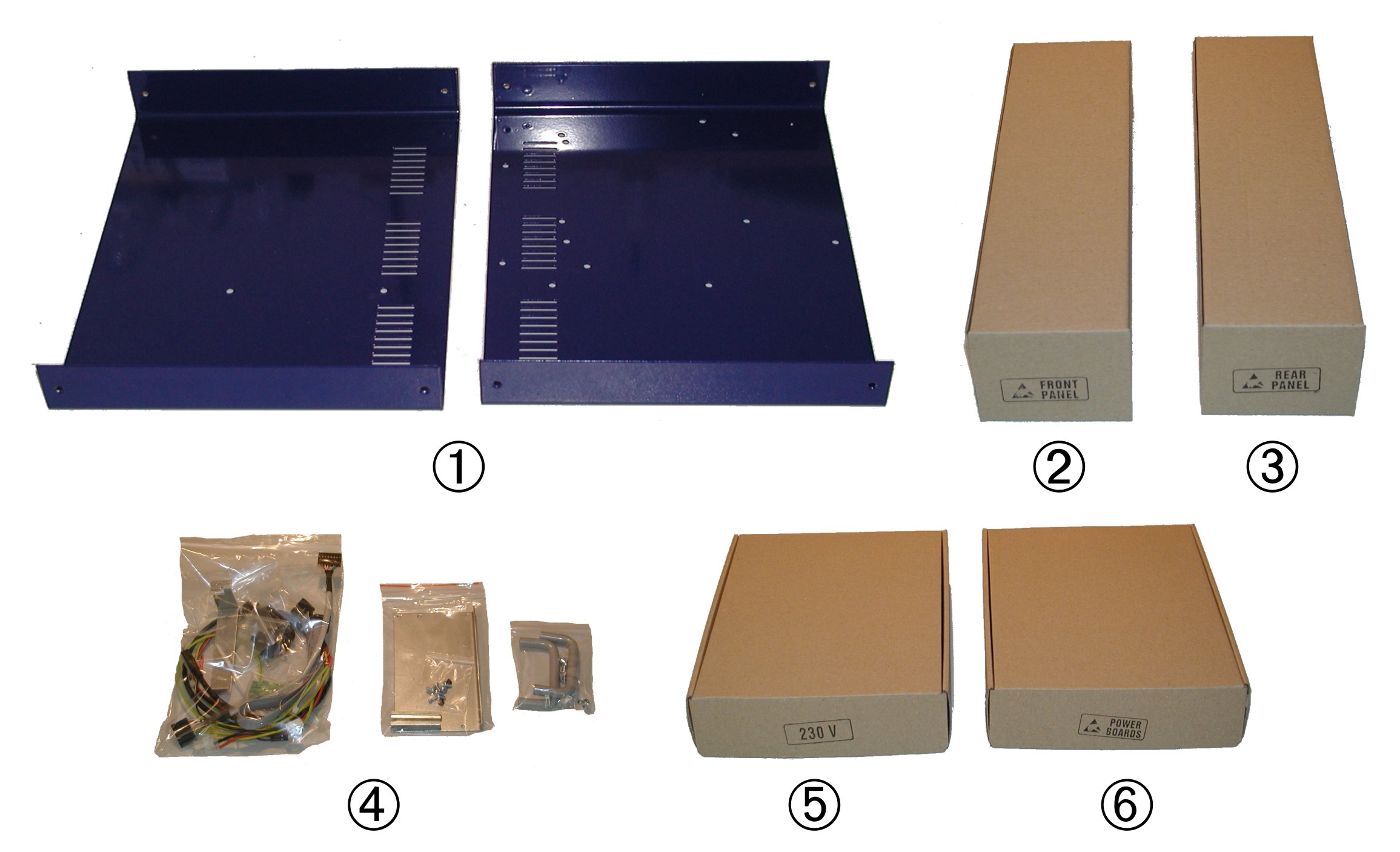
Please note that they comes in cardboard box with voltage stamped on (see Fig. 1, item 5), but that voltage denote fuse ratings only (i.e. 4 A for 230 Vac or 8 A for 115 Vac). If you are going to use it with 115 Vac you have to change switch position as described in section AC/DC modules.
Kit assembly steps
- Package content
- Plastic bags content
- Bottom plate
- Rear panel
- AC/DC modules
- Front panel
- Power boards
- Final steps
- Powering up, calibration and firmware upload
- Troubleshooting
The PSU complete kit consists of the following parts, as shown in Fig. 1:
- Top and bottom plates
- Front panel box
- Rear panel box
- Plastic bags with wire harness and miscellaneous mounting parts
- AC/DC modules box
- Power boards box
- Extra parts (for EEZ H24005 enclosure kit only!)
Please note that AC power cord is not included into this kit.
Rear panel box contains enclosure’s rear panel with mounted AUX power module, IEC AC inlet, 60 mm cooling fan with finger guard and Cable Set #2.
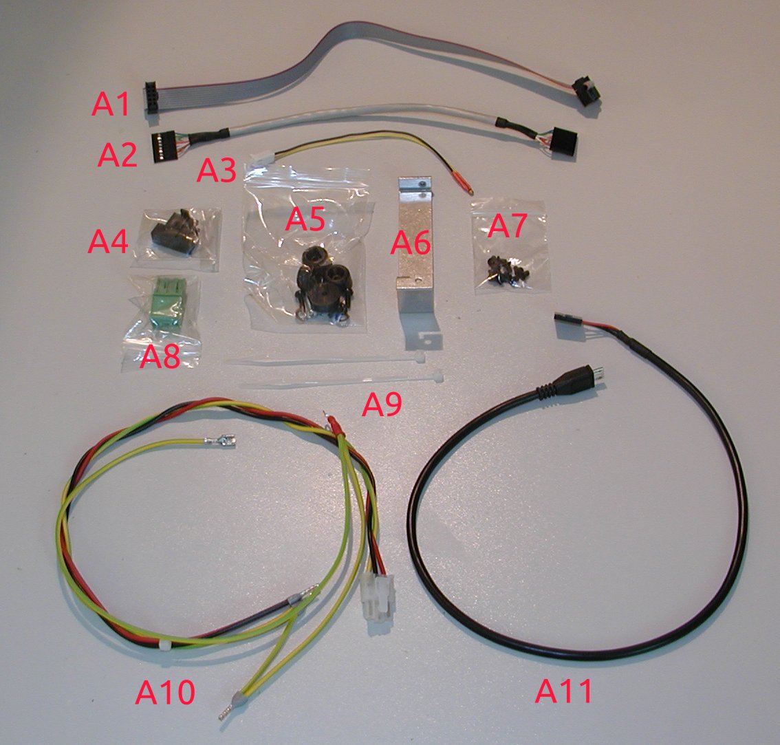
Before start assembling please take some time to check if content of plastic bags includes all what is listed below. Also familiarize with Position naming that will be used in the rest of the document.
|
Position |
Description |
|
A1 |
10-pin IDC cable (AUX power module – Arduino Shield) |
|
A2 |
Ethernet patch cable (AUX power module – Arduino Shield) |
|
A3 |
AUX temperature sensor (Arduino Shield) |
|
A4 |
Fuse drawer (IEC AC inlet) |
|
A5 |
Enclosure feet pack |
|
A6 |
AC&DC module connector cover |
|
A7 |
M3 x 5 mm bolts for enclosure (11 pcs) |
|
A8 |
DOUT2 plug-in connector (AUX power module) |
|
A9 |
Polyamide cable ties (2 pcs) |
|
A10 |
|
|
A11 |
Micro USB to 5-pin 0.1” header cable (AUX power module – Arduino Shield) |
|
Position |
Description |
|
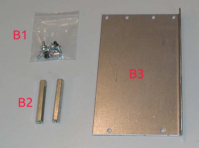
B1 |
AC/DC modules mounting bolts: M3 x 5 mm black countersunk head (4 pcs) and M3 x 5 mm (7 pcs) |
|
B2 |
40 mm spacers (2 pcs) |
|
B3 |
AC/DC modules mounting rail (Varisom) |
Please note that only two instead of four bolts with countersunk head are mistakenly delivered with Complete kit. Therefore use that two bolts to fix mounting rail (B3) to the enclosure’s bottom plate, and leave lower end of 40 mm spacers (B2) unfixed. In such way AC/DC modules will stay securely fixed.
|
Position |
Description |
|
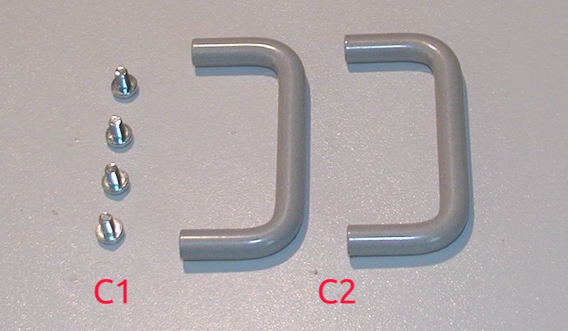
C1 |
M4 x 6 mm mounting bolts (4 pcs) |
|
C2 |
Enclosure front panel handles (Varisom) |
Extra parts (for enclosure kit only)
This section is related only for buyers who ordered so-called Enclosure and Assemblies kit. It comes with few extra parts that together with the following items is required to get completely functional PSU:
- AC/DC modules (LRS-150-48 or auto-switch LRS-150F-48) x2
- Assembled core modules (i.e. Aux power module, Power board x2, and Arduino Shield)
- 3.2” TFT color touchscreen display and
- Arduino Due compatible board
For more details please refer to EEZ PSU H24005 building instructions (r5B12).
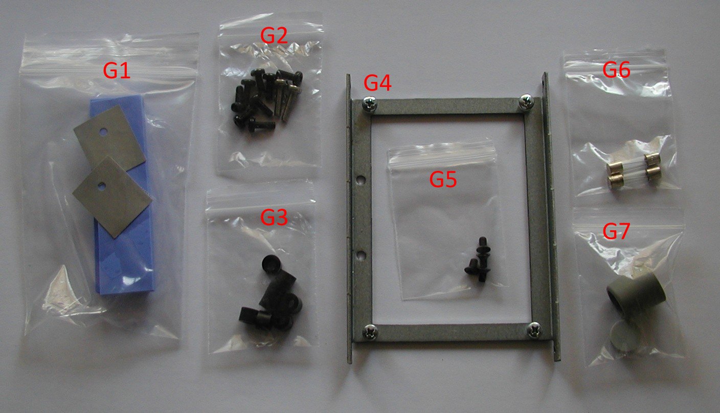
Extra parts are shown on Fig. 5. Additionally a set of two custom made heatsinks are included into this kit.
|
Position |
Description |
|
G1 |
0.4 mm (for Q4) and 5 mm thermal silicone pads |
|
G2 |
Set of bolts for Power boards mounting to the heatsinks |
|
G3 |
5 mm spacers for Power boards |
|
G4 |
3.2” display mounting frame (Varisom) with bolts and 2 mm spacers |
|
G5 |
M3 x 5 mm bolts for display (4 pcs) |
|
G6 |
Set of fuses (230 Vac or 115 Vac as stated on cardboard box) |
|
G7 |
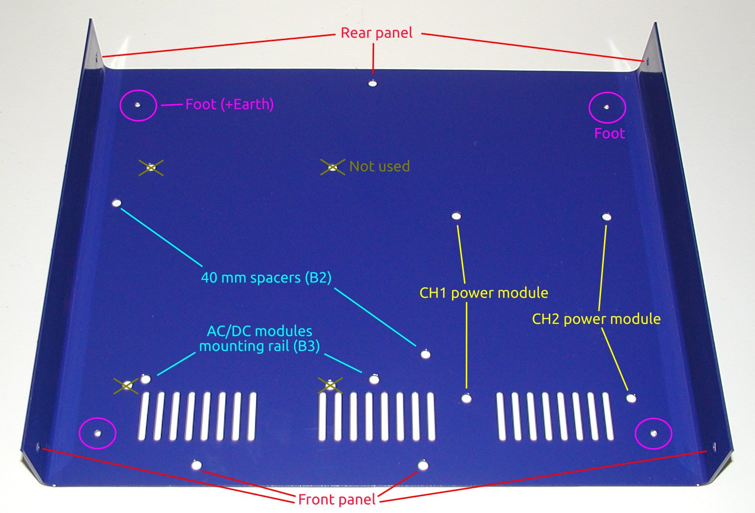
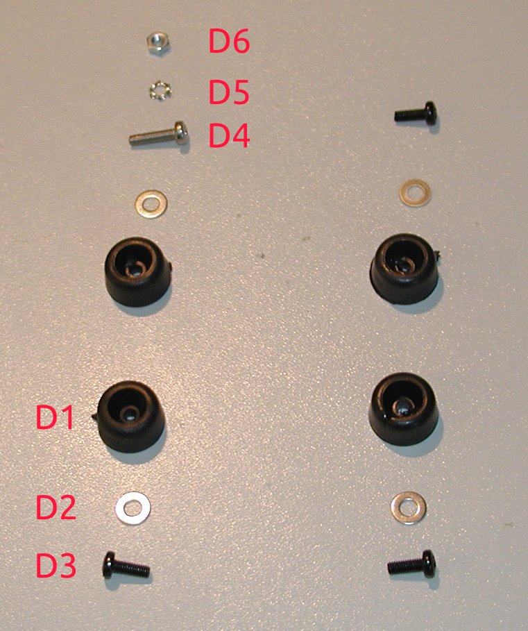
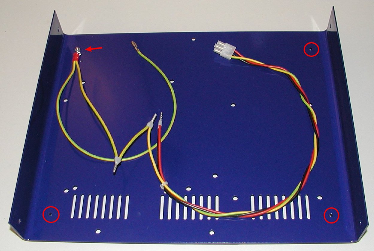
In this step rubber feet (D1, Fig. 7) will be mounted and protective earth will be attached to the enclosure. Identify enclosure bottom plate using the Fig. 6 and prepare items A5 and A10.
Content of A5 is shown on Fig. 7. Please note that longer bolt (D4) and additional parts (D5, D6) should be used for making contact with protective earth wire on the foot hole that is near the AC inlet (see note Foot (+Earth)).
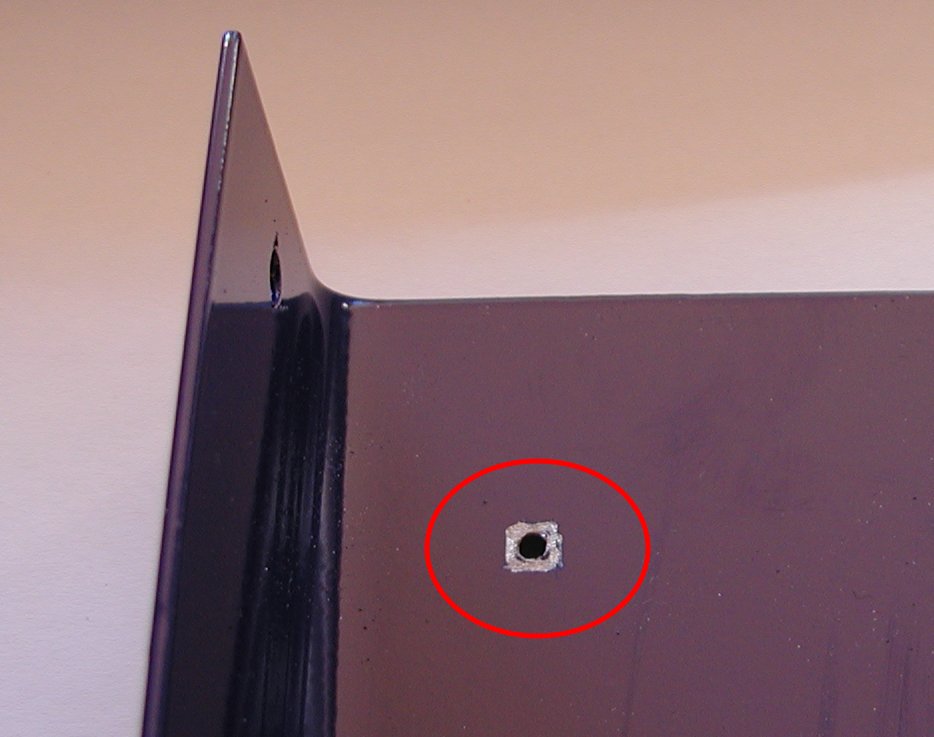
Use M3 black finish bolt (D3) and washer (D2) for mounting feet (D1) on the holes with M3 thread (see red circled hole on Fig. 9). The paint around latest hole where protection earth will be connected can be previously carefully removed to ensure even better electrical contact then externally serrated washer (D5) could provide (see Fig. 8).
For protective earth connection mount last foot with long bolt (D4) first and then place ring terminal (item A10) on inner (top) side of the bottom plate between serrated washer (D5) and M3 nut (D6). Check with ohmmeter if low resistance connection is established between earth wire on A10 and bottom plate (when complete enclosure is assembled you can repeat this by testing conductance between earth pin on IEC AC inlet and top plate).
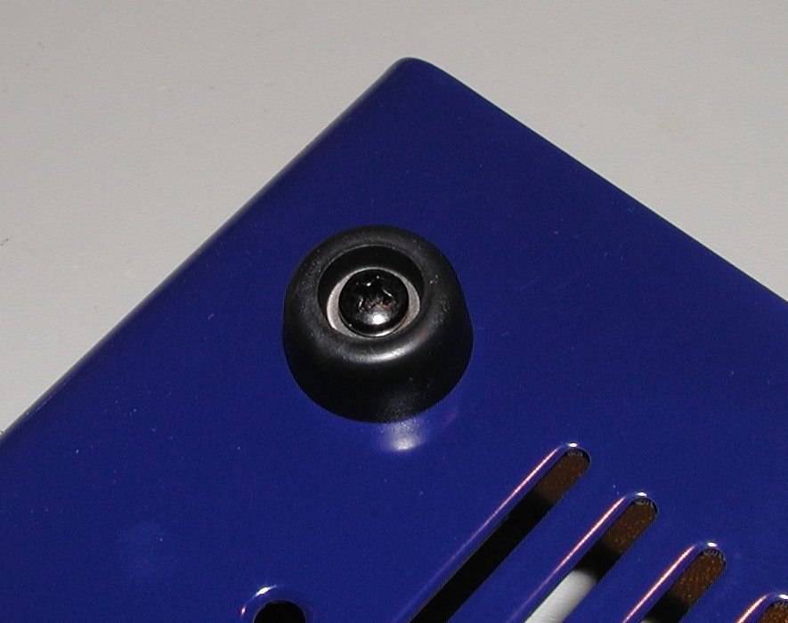
Fig. 9 shows bottom plate with protective earth mounted and Fig. 10 how robber foot looks like when mounted. Take into account that bolt should be screwed enough that its head is not above foot.
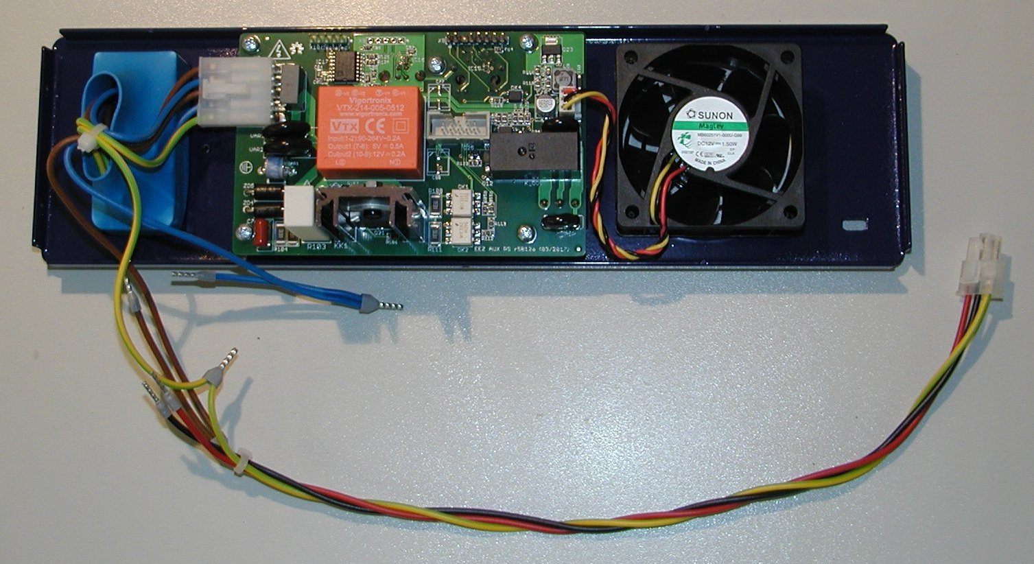
Remove rear panel from its cardboard box (item 3) and check if it looks as shown on Fig. 11. It should include IEC AC inlet (with AC switch patch cables that is not visible due to blue heatshrink tube), AUX power module with 5-pin AC plug and 3-pin cooling fan receptacle connected, 60 mm cooling fan and Cable set #2 connected.
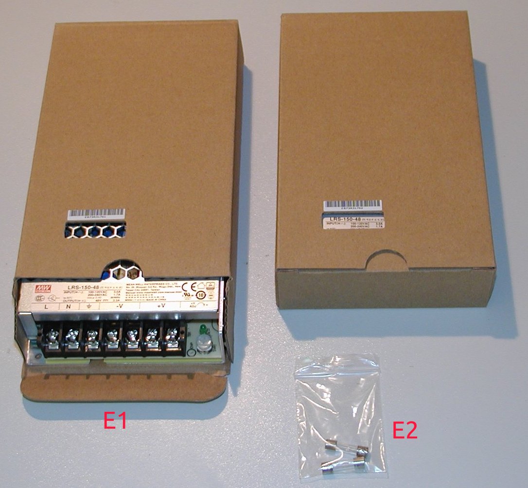
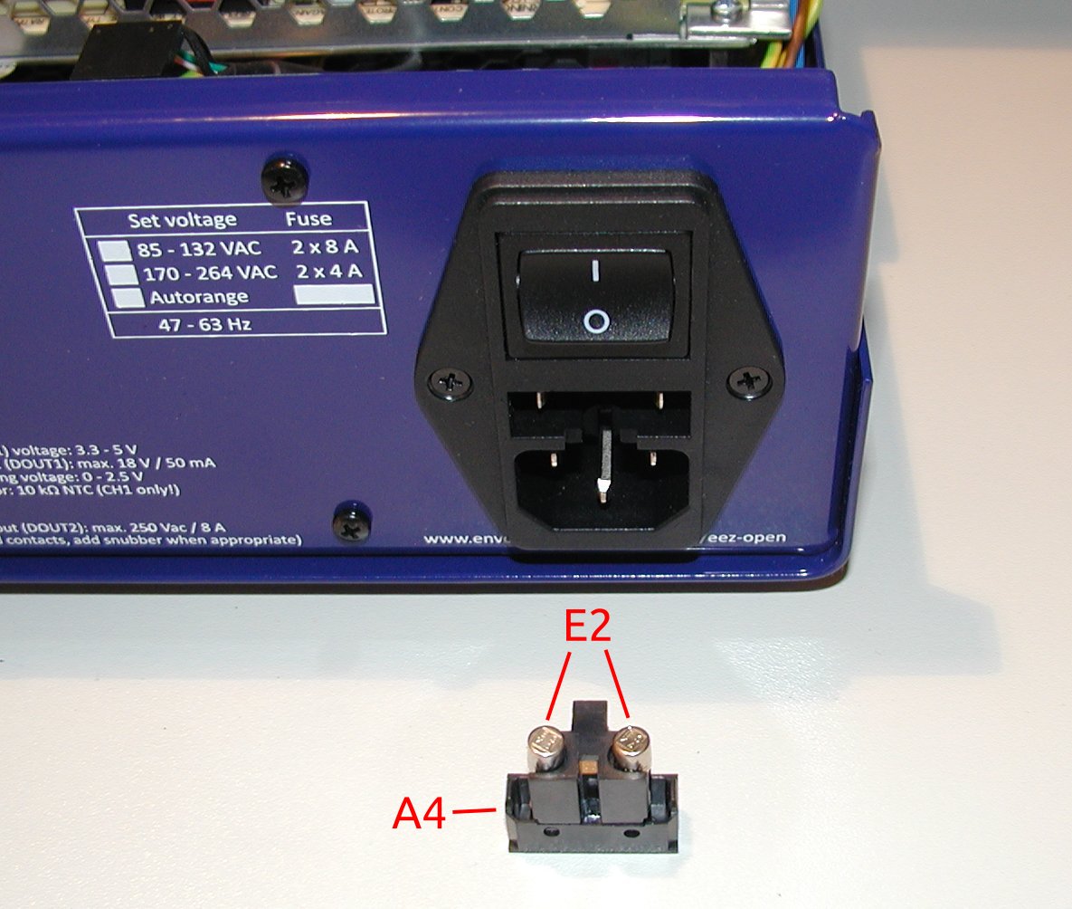
The IEC AC Inlet has power switch and place for fuse drawer that carry two fuses. Fuse drawer is packed separately (item A4) and supplied two fuses (item E2, see Fig. 14) should be in accordance with AC mains voltage in your country (4 A for 230 Vac or 8 A for 115 Vac).
Do not insert fuse drawer with or without fuses before everything else is assembled.
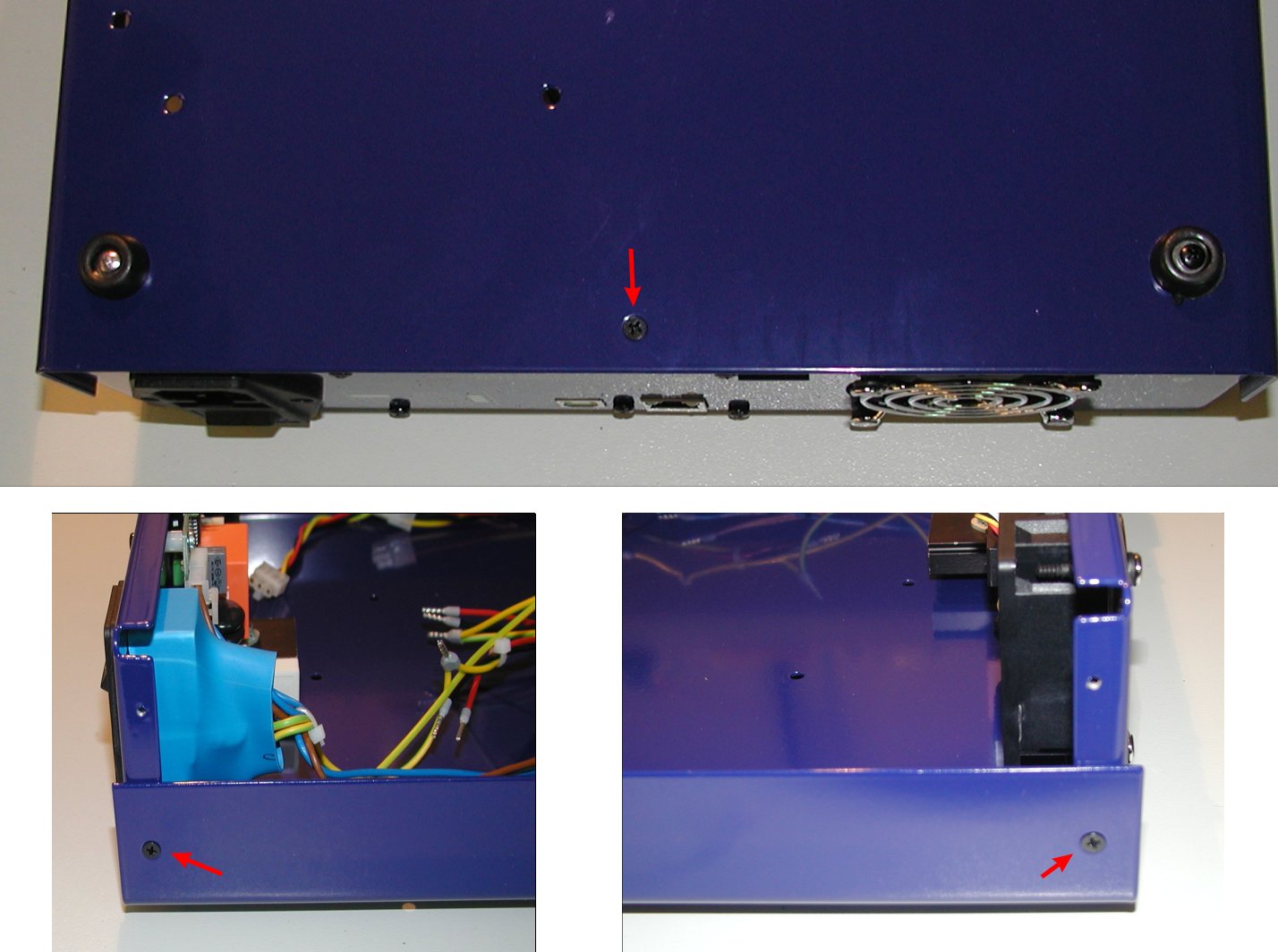
If you didn’t notice any issues with rear panel parts you can proceed with mounting it to the previously prepared bottom plate by using three bolts from A7 and fix it into positions shown on Fig. 12.
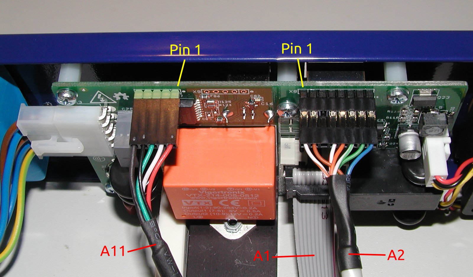
Finally you can attach cables A1, A2 and A11 to the AUX power module as shown on Fig. 13.
Unpack box with AC/DC modules (item 5) and check if it contains items shown on Fig. 14.
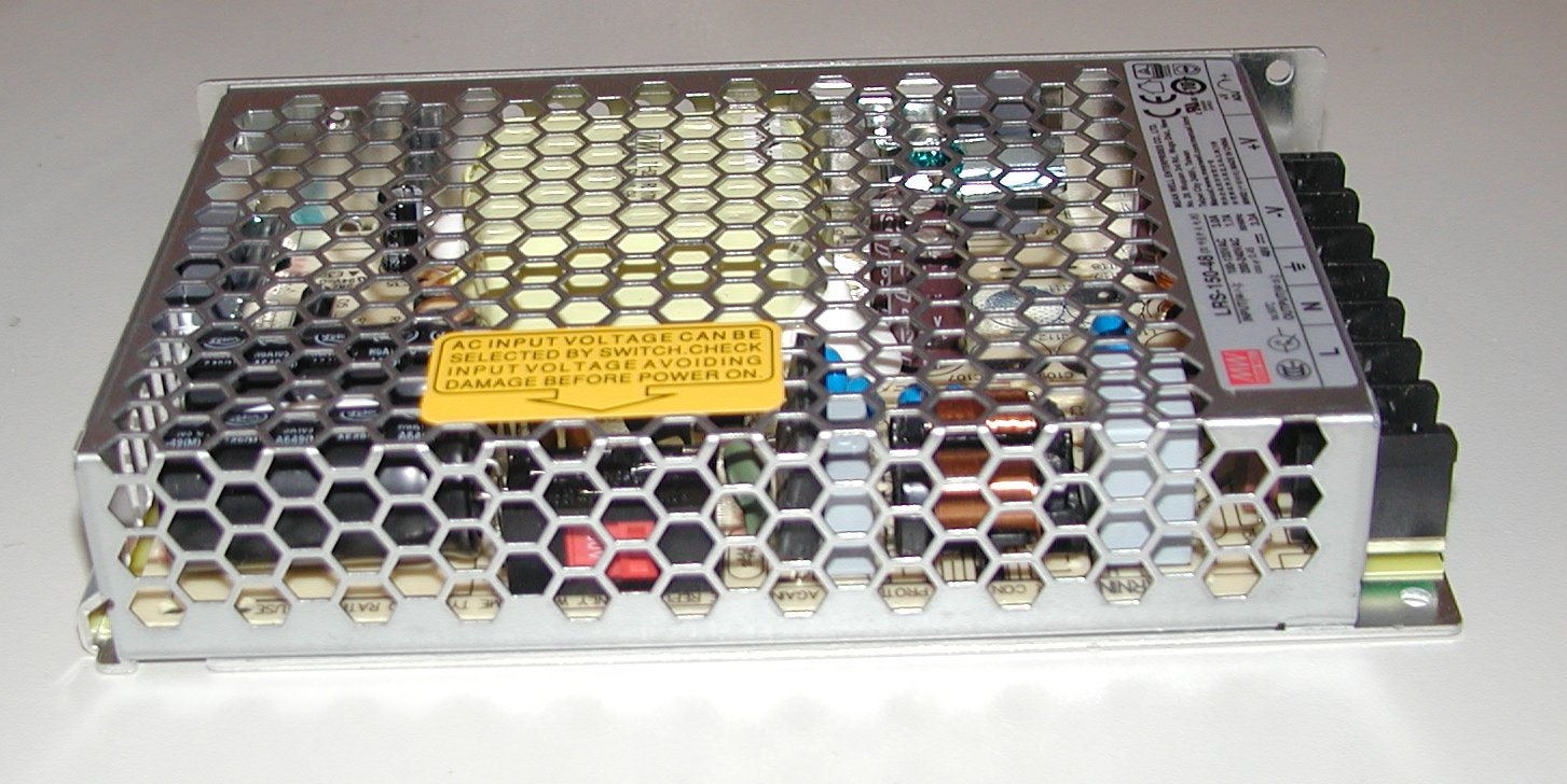
Before proceed with assembly be sure that AC input voltage selection switch (Fig. 15) is properly set. This is especially important if your AC mains voltage is 230 Vac because if switch is set to 115 Vac it is possible that applied mains damage AC/DC module permanently (don’t count with blown fuses here!).
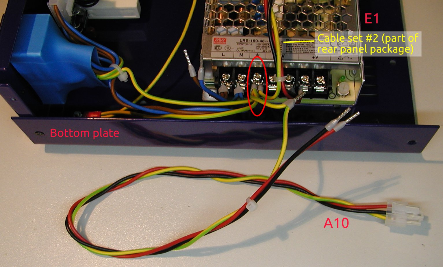
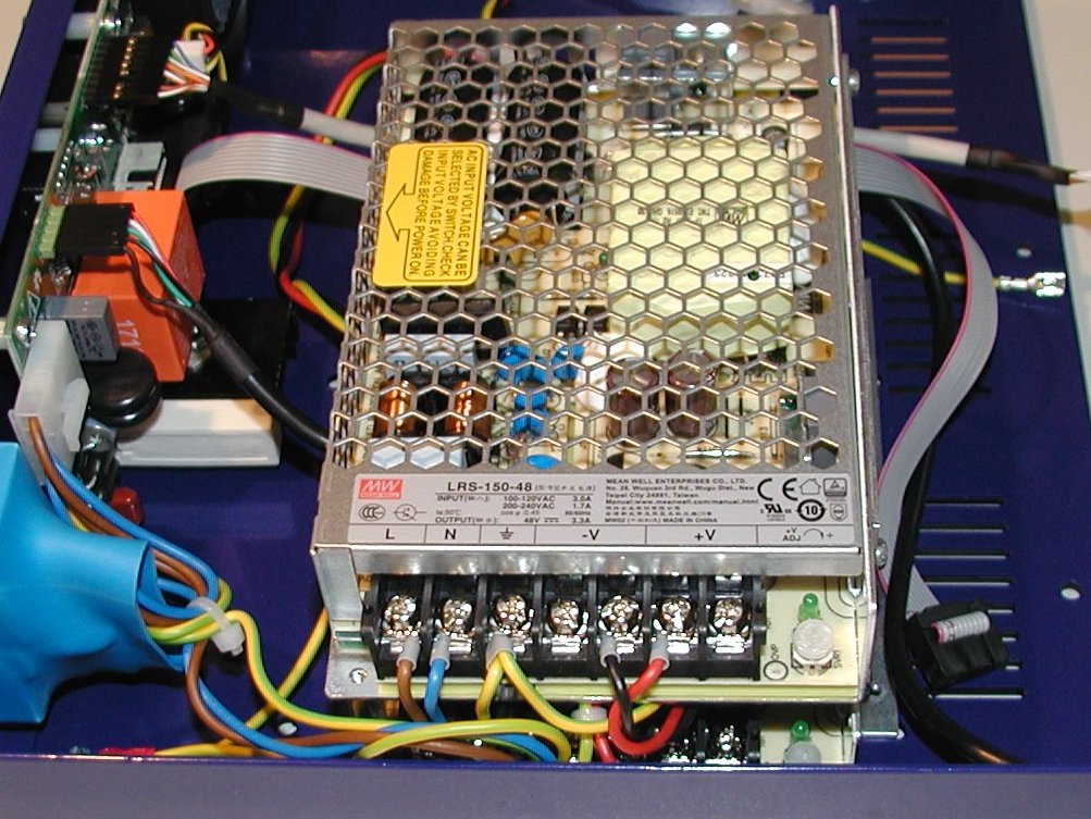
Put aside for the moment E2 and take one of E1 to connect on them Cable set #2 wires as follows:
|
Name |
Position |
Color |
|
AC line input |
L |
Brown |
|
AC neutral input |
N |
Blue |
|
Protective earth |
(Earth sign) |
Yellow-green |
|
DC output negative |
-V |
Black |
|
DC output positive |
+V |
Red |
Take also protective earth wire from Cable set #1 (item A10) and mount it on the same position as protective earth from Cable set #2 (see red cycle on Fig. 16).
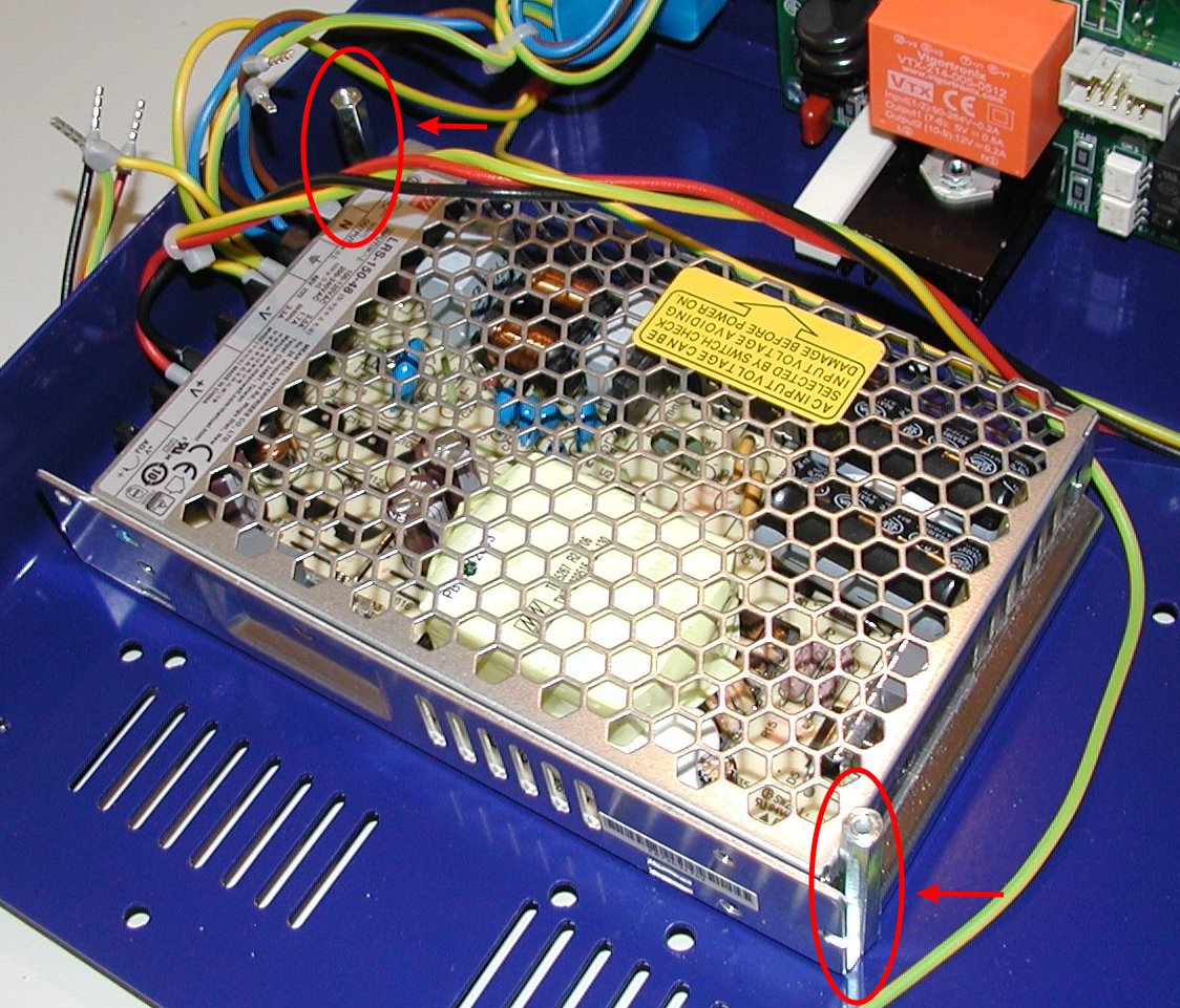
When first (lower) AC/DC module wiring is completed you can proceed with fix it to the final place on the bottom plate by using two M3 bolts with black countersunk head (from B1) and metal spacers (B2).
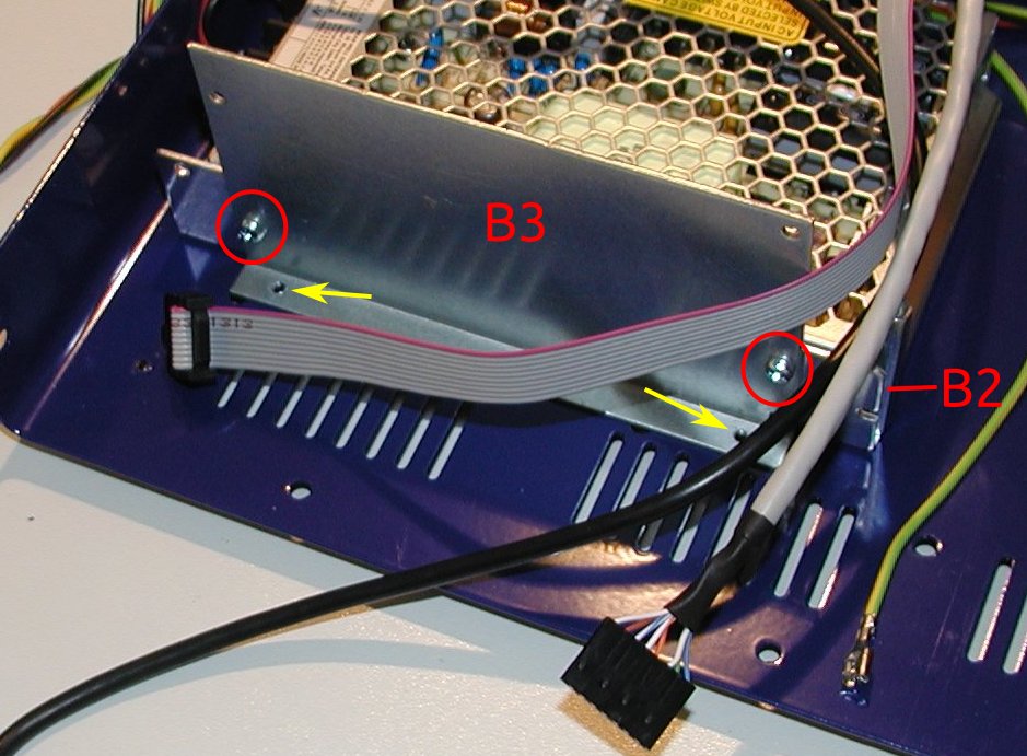
Next step will be attaching AC/DC mounting rail (B3) with M3 bolts (from B1) to the AC/DC module and bottom plate as shown on Fig. 18. AC/DC module has three M3 holes on the side, only two bolts for mounting (red encircled), and another two with black countersunk head (also from B1) for fixing it at the bottom plate (see yellow arrows and Fig. 6).
Second AC/DC module can be now installed on top of the first (lower) one. First connect remaining wires from A10 and Cable set #2 as shown on Fig 20.
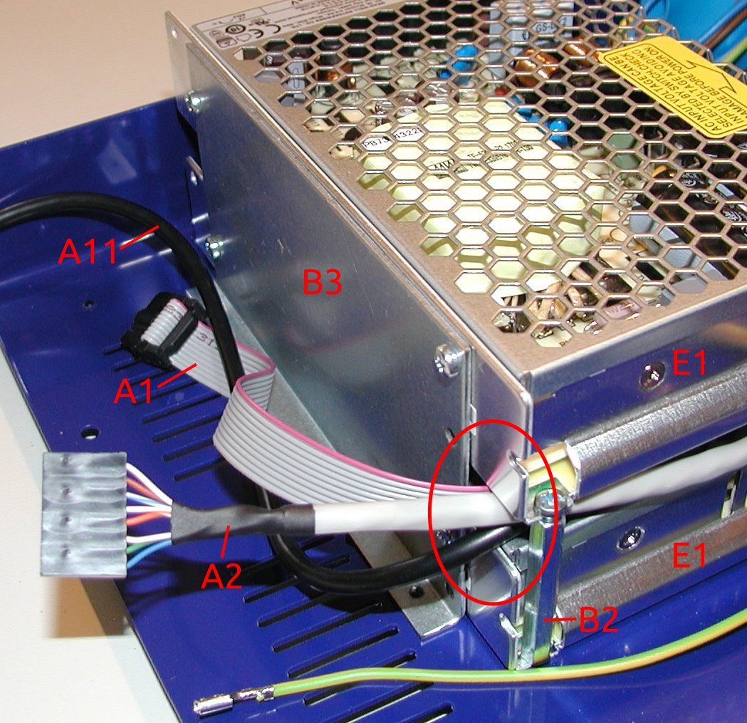
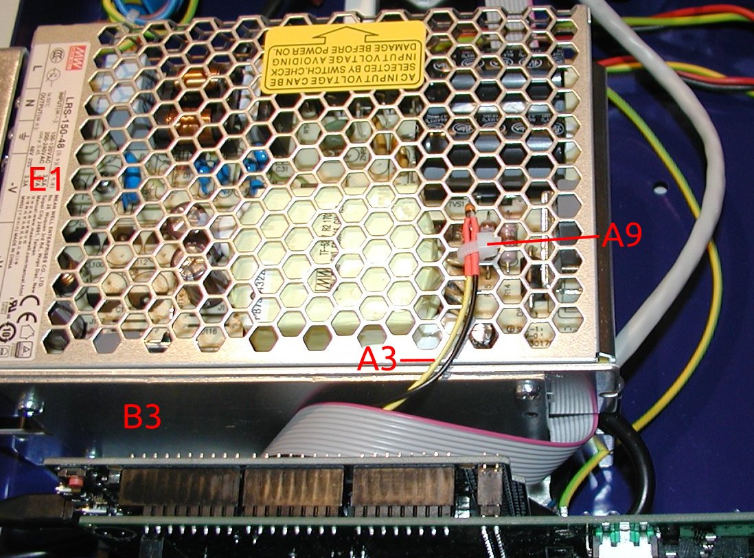
Before proceed with fixing second AC/DC module to mounting rail (B3), you can insert all cables that goes to Arduino Shield mounted on the front panel (see red encircled hole on Fig. 19 made by B3, two E1 and B2). You can use one of cable tie (A9) for that (spare another one for AUX temperature sensor A3).
Use two M3 bolts from B1 for fix second (upper) AC/DC module on the side. Use another M3 bolt for fix it only on the spacer B2 that is visible on Fig. 18. Fixing on the next spacer will be performed in the next step.
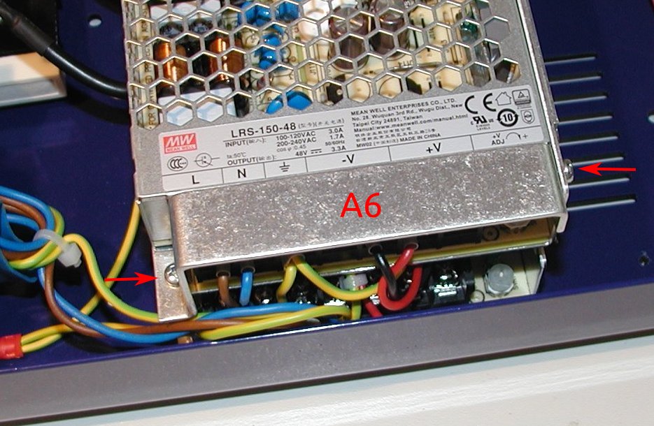
Final step in AC/DC modules mounting is to put a cover (item A6) over second (upper) AC/DC module terminals as an additional safety measure against electric shock when you decide for any reason to operate the PSU with top plate removed. Use two remaining M3 bolts (from B1) and fix it on the places marked with red arrows on Fig. 21.
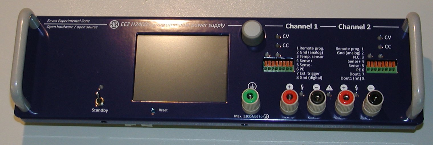
The front panel box content is shown on Fig. 22 that is enclosure’s front panel with mounted Arduino Shield with Arduino Due board, 3.2” TFT touchscreen color display and 4 mm binding posts for power outputs and protective earth.
A first step for the front panel assembly is mounting of handles (item C2). Use two M4 bolts (C1) to fix it on the front panel’s ends. Fig. 23 shows how front panel looks like with handles mounted.
Attach the front panel very loosely to the bottom cover to avoid issue with mounting Power boards lately (see issue #52).
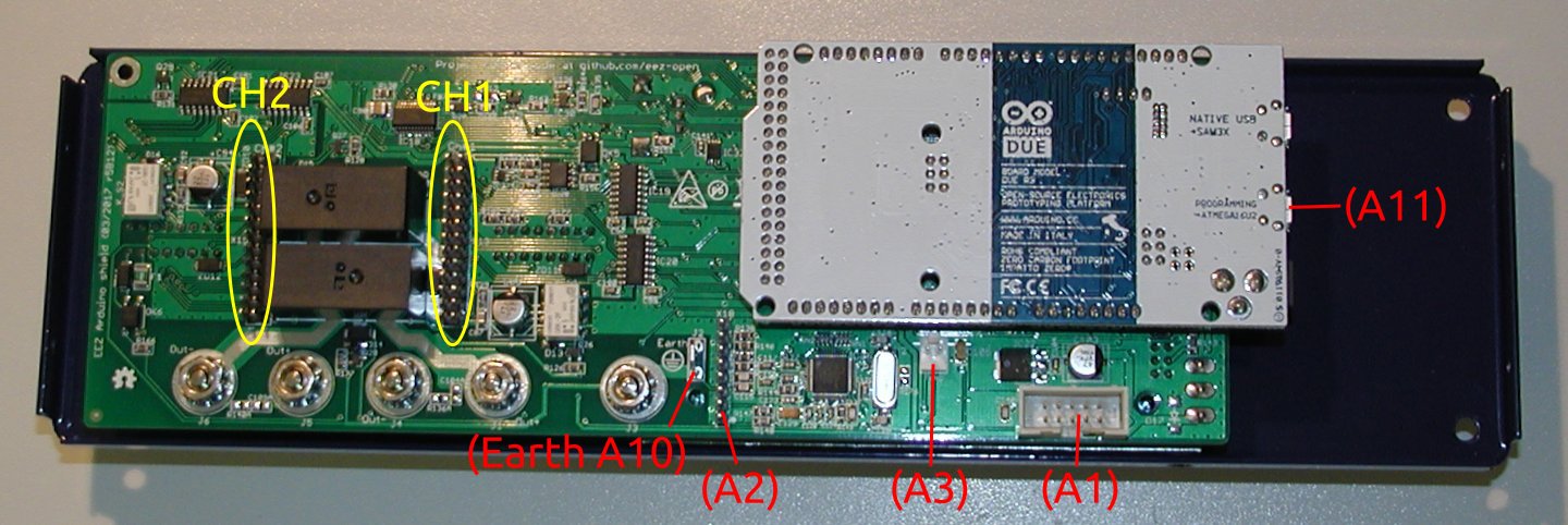
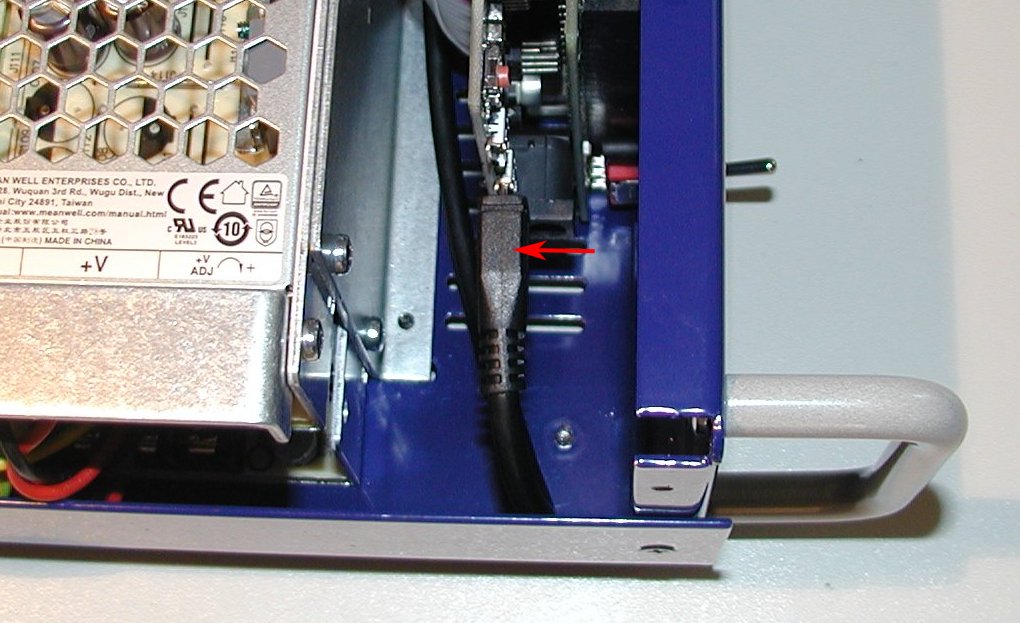
A next step should be wiring of the Arduino Shield (use red colored text on Fig. 22 as reference). That also include AUX temperature sensor (item A3). Take a special care when inserting USB cable (A11) to the Programming port (lower one) on the Arduino Due to not damage micro USB socket. It’s recommended to bend USB cable appropriately before insertion to lower its pressure when it is put into place (Fig. 25).
Use Native port (upper one) with firmware v1.01 or latter. If you still want to use programming port add the following code into your conf_user.h file:
	#undef CONF_SERIAL_USE_NATIVE_USB_PORT
	#define CONF_SERIAL_USE_NATIVE_USB_PORT 0
Use four M3 bolts (from A7) to join front panel with bottom plate following the holes marked on Fig. 6 and Fig. 26
When front panel is mounted to the bottom plate it’s possible to fix AUX temperature sensor (A3) someplace above AC/DC modules as shown on Fig. 27. Use one cable tie (A9) for that.
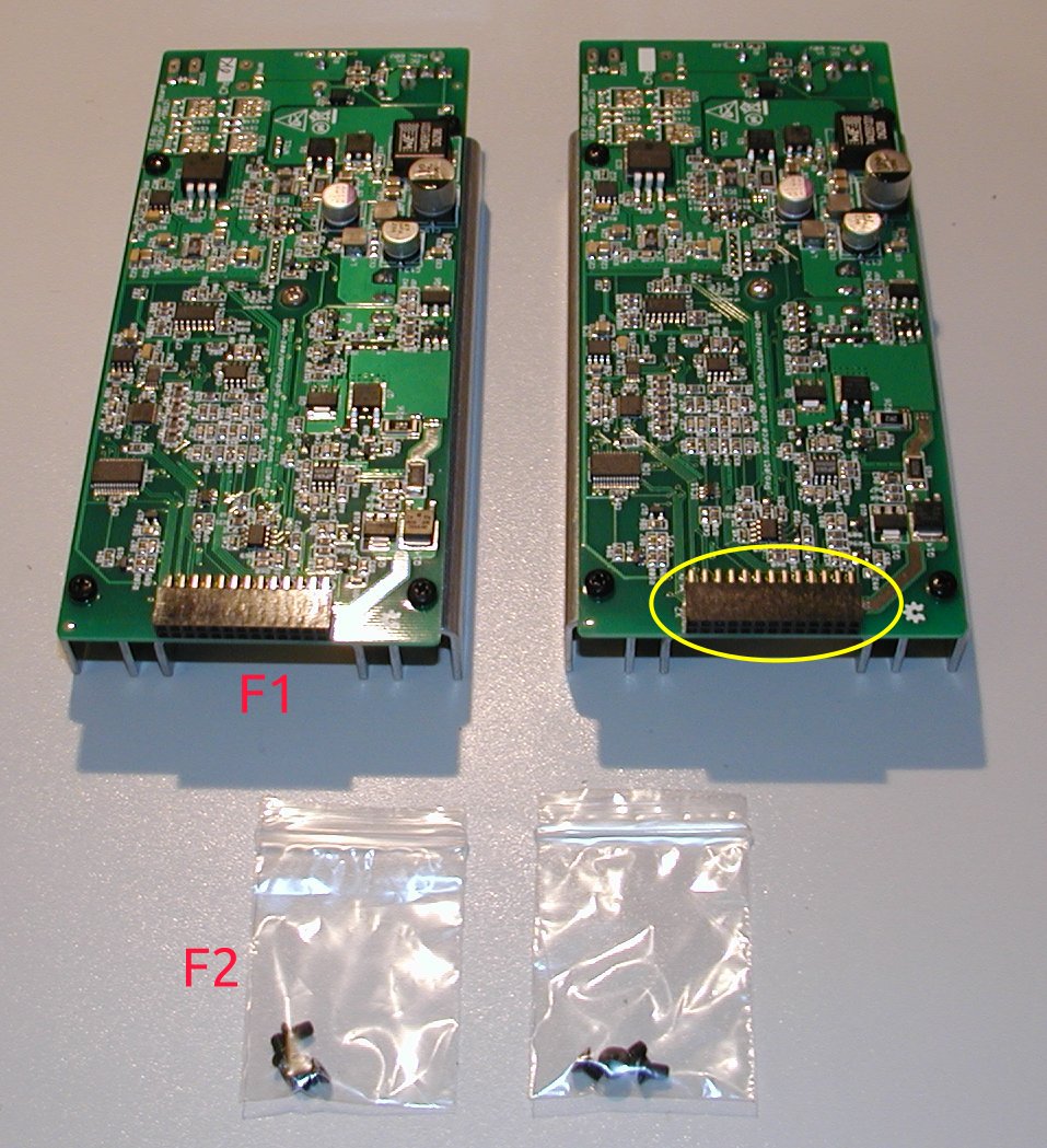
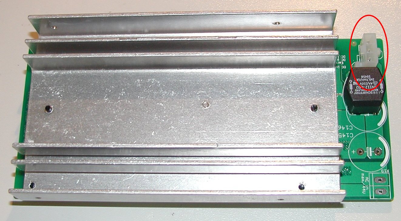
The Power boards cardboard box contains two Power boards (F1) and M3 bolts (F2) used for mounting. Before mounting power boards to the bottom plate (check Fig. 6) plug in the DC power cable (+48 V) to the DC input connector (red encircled on Fig. 29).
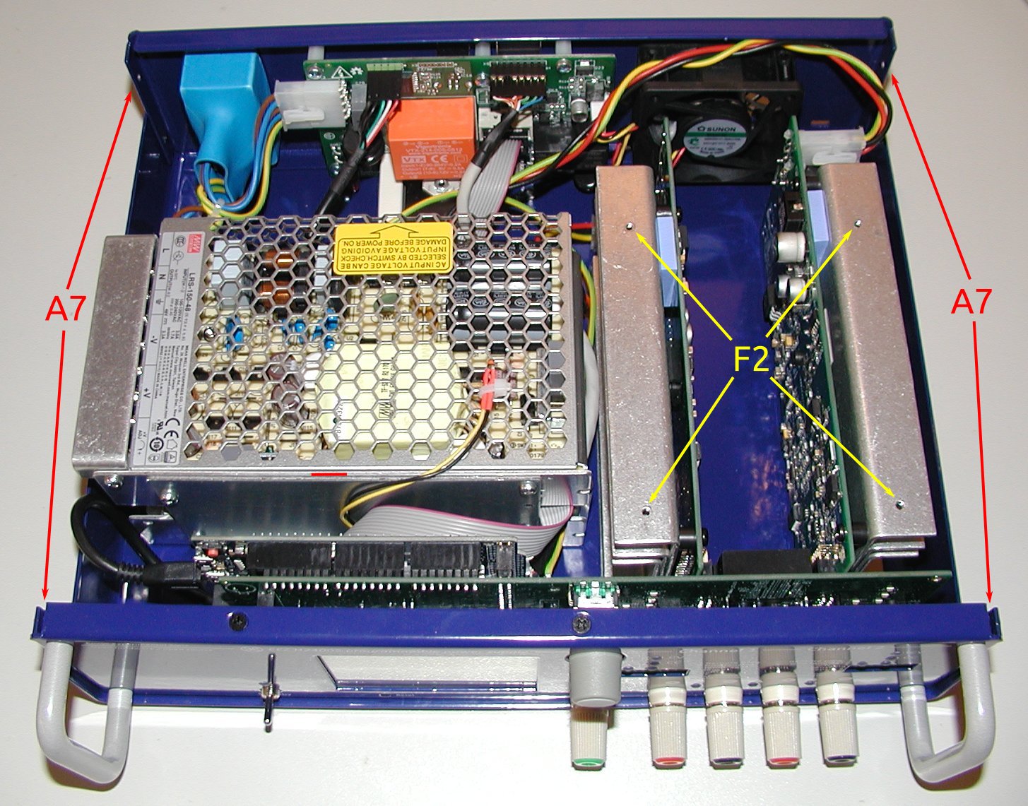
Now you can carefully insert it into Arduino Shield (Fig. 21) that PCB components side is facing toward cooling fan center as shown on Fig. 30. Double check that no misalignment between 26-pin header on the Arduino Shield and Power board’s receptacle (yellow encircled on Fig. 28) exists.
The PSU with all parts mounted is shown on Fig. 30. Covering it with top plate and placing fuses into AC inlet is now only what is left.
You’ll need eight M3 bolts with black countersunk head (from A7 and F2) for mounting top plate.
Check fuses (E2) rating (i.e. 8 A for 115 Vac and 4 A for 230 Vac) before placing them into fuse drawer (A4) as shown on Fig. 31.
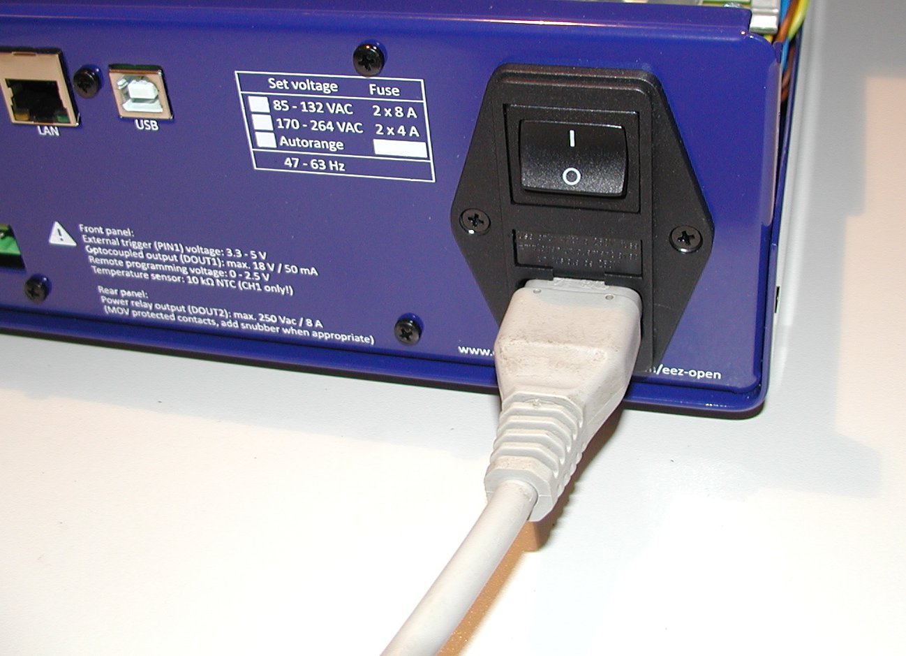
Mount fuse drawer into IEC AC inlet on the rear panel and insert AC mains power cord (it’s not a part of this kit!) as shown on Fig. 32.
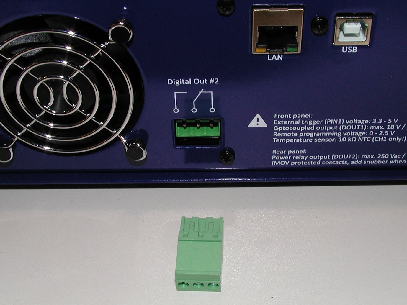
The PSU has on the rear panel a 3-pin connector for Digital out #2 (DOUT2). You can use A8 plug with screw terminals to make connection with external circuits (Fig. 33).
The PSU complete kit comes with firmware v1.0 loaded into Arduino Due board. For further uploads please follow instructions here. The list of firmware release can be found on the GitHub.
Powering up, calibration and firmware upload
Do not start PSU for the first time with any load connected!
First test output voltage programming. When set output voltage is within expected tolerance (i.e. up to 5 % not calibrated) you can continue with testing output current capability. Choose output voltage and load combination that output current at start is not higher then e.g. 100 mA. If reading is within expected tolerance, you can proceed with higher load up to 5 A per channel.
The Power board outputs are not calibrated. At the first start you will be asked about calibration but you can postpone it. Each output has to be calibrated separately and you can access calibration wizard from System page or from Channel’s info page (Fig. 34).
The calibration wizard will guide you through all steps after you successfully entered calibration password (default is eezpsu). Voltage set for current calibration is 20 V (middle of the range) therefore you have to use resistor lower then 4 Ω that can dissipate enough power (example1, example2 both of them must be installed on heatsink!).
Please note that high current (5 A) range calibration could be a rather tricky since output current is going to decrease over time as shunt resistor is heating up. That is a known issue (see hardware issue #40 and suggestion for compensation in firmware reported in #100). Depends of what end result is more acceptable, you can enter output current value that is measured immediately after the load is connected, or you can wait up to few minutes (e.g. before fan is started to work) and measure the output current.
Uploading your firmware to the latest release is highly recommended. Uploading process is described under Firmware uploads section of the EEZ PSU H24005 building instructions (r5B12) document.
A short video about installing Arduino IDE and firmware components on Win10 is available here.
- Display is not working – during displays testing we found on considerable number of them that they pins have to be degreased. It’s possible that your display’s pins are not degreased enough, or lost contact due to mechanical shocks in transportation. Detach it from front panel and Arduino Shield board first, and try to clean pins with cleaning/degreasing spray (e.g. Kontakt WL). Pay special attention to make sure that cleaning agent not penetrate between display and it’s PCB. That could create a visible spot when display is turned on (if cleaning agent is not aggressive that should be a temporary issue. Wait some time that cleaning agent simply evaporate).
- Display colors are “washed out” – it appears that for used “noname” display backlight and colors intensity could vary considerably. While testing we found about half of dozen different level of backlight intensity. We tried to rectify that to some extend by offering display brightness and background color (i.e. the blue one) luminosity settings. You can find that parameters under system settings page 2 as shown on Fig. 35. We tried to set the most appropriate luminosity level for your display. The default value is 15 but if your found here e.g. 10 (for firmware v1.0) that means that your display is unfortunately is too bright (hence lower value). In that case the real “cure” is to start hunting for better unit on eBay or similar online shops.
- Output voltage is above max. range (e.g. 42-43 V) – voltage regulation is failed, possibly due to faulty bias power supply. Switch the PSU off immediately and check V+ and V- outputs of IC4 (on ferrite beads FB2 and FB3). It’s highly possible that IC4 thermal pad is not soldered properly and that mechanical shock (e.g. in transportation) cause lost of electrical contact. It’s output voltage has to be a little above 5 V (if you’re perfectionist replace R20 and R25 with 316 K), but if IC4’s thermal pad, that is also its ground connection, is not connected you can expected e.g. about +12 V on V+ and -0.5 V on V- line. If that happen it’s also possible that IC12 is damaged permanently (start up self-test procedure will report DAC failure in that case). Another possible collateral damage could happed if load is mistakenly connected. That can easily damage low current switch and sense resistor (Q13 and R63).
If IC4 reflow soldering work is necessary detach PCB from the heatsink and remove thermal pads first! - Output current cannot reach max. value (i.e. 5 A) with load connected – if Power board output cannot deliver max. current for more then 10 seconds or cannot reach max. current with output current step is programmed (e.g. from 0 to 5 A) then probably something is wrong with switching pre-regulator on the first place. We found on dozen of Power boards that came from manufacturer that C14 is not soldered properly or is dropped off the PCB. Without it pre-regulator cannot manage to deliver more then about 3 A. Another possibility is that IC1 thermal pad is not properly soldered (similar to above mentioned IC4). You have to be ready for some resoldering work with hot air. If max. output current cannot reach more then 1.5 A please check Q13 and Q14 first, before going to do anything with IC1. Even if you need to desolder them for testing purposes it’s still less cumbersome then resoldering IC1.
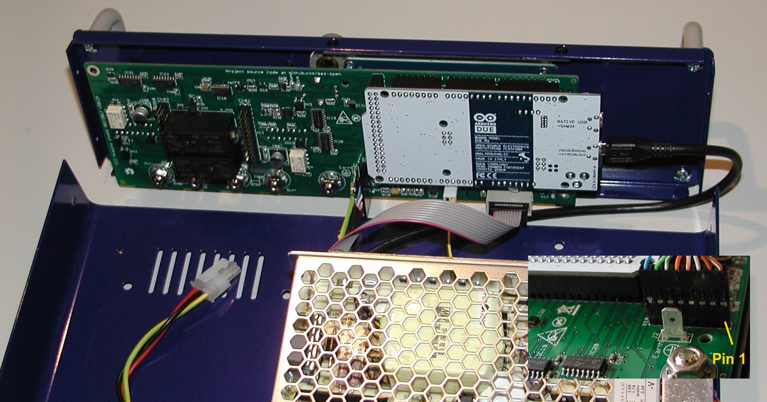
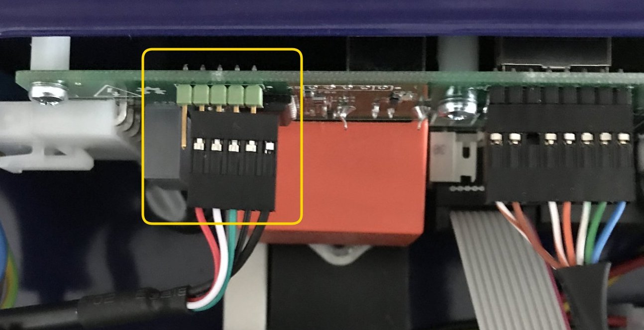
If IC1 reflow soldering work is necessary detach PCB from the heatsink and remove thermal pads first! - USB cable is shutting down a whole unit – unfortunately your USB patch cable is faulty. Please check wiring pin by pin (i.e. check if red wire is connected with +VUSB, black with GND, etc.).
It’s possible that you have to rotate it as one user suggested as shown on Fig. 36. If that is not acceptable, you can try to detach pin by pin from the header and put them on the right place.
- Channel enters unregulated mode (neither CV nor CC when output value is displayed in red color) for programmed output voltage below ~1.8 V. Replace R20 and R25 with 316 K as suggested in issue #42 on the GitHub.
- Output current cannot reach max. value of 5 A on step load – that can be check by set output enable with connected load, or by connecting load when output is already enabled. Make sure that used load is low enough that channel enters CC mode. For example use 3.3 Ω with output set to 20 V and current set to maximum. Try to replace pre-regulator current sense resistor R4 with another one (we found on few boards that comes from manufacturer that R4 resistance is too high despite the fact that marked value is correct (i.e. 10 mΩ).
A work in progress

